30
MAX Arm/Ultra Arm V1
EXIT PWR
ALARM
POWER /
SOLAR IN
BATTERY
INPUT
B
PR
S
M
S
BATTERY
INPUT
ERROR
BATTERY
IN USE
POWER
B
RESET
ID
PLUG
MODULE
PORT
FIRE DEPT
RADIO GND
RADIO SIGNAL
ID PLUG
ERROR
24VDC OUTPUT
12VDC OUTPUT
GND
GND
GND
LOOP
LOOP PWR
LOOP
CENTER
SAFETY
OF
SING
1
2
3
4
5
6
7
8
9
10
OFF
1
2
3
4
5
6
FAULTS
OFF
EXIT LOOP
MODE A
MODE B
12
loops & loop detectors
11
Adjust ERD Reverse sensor
MAX
SENSE
ERD SENSITIVITY
MIN
16
3
1
14
12
9
7
MAX
SENSE
ERD SENSITIVITY
MIN
16
3
1
14
12
9
7
MAX
SENSE
ERD SENSITIVITY
MIN
16
3
1
14
12
9
7
MAX
SENSE
ERD SENSITIVITY
MIN
16
3
1
14
12
9
7
MAX
SENSE
ERD SENSITIVITY
MIN
16
3
1
14
12
9
7
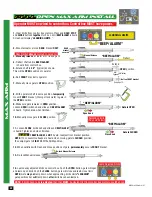
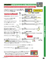
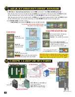
The ERD Sensor - Electronic Reversing Device (Type A) MUST be adjusted for the OPEN and CLOSE gate cycles.
When the gate encounters an obstruction during the CLOSE cycle, it will reverse to the open position and PAUSE the gate.
An input command (press remote button or exit loop) is needed BEFORE the gate will reset and close again.
When the gate encounters an obstruction during the OPEN cycle, it will reverse approximately 6 inches and PAUSE the gate.
An input command (press remote button or exit loop) is needed BEFORE the gate will reset and open again.
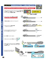
For the ERD Sensitivity to function correctly:
•
Gate positions must be learned BEFORE adjusting the ERD Sensitivity.
A. Turn knob until blue LED lights up.
Maximum sensitivity reached,
Position 1 - Too sensitive for most gates.
Position 12:
•
Typical gate setting.
B. Turn knob counter-clockwise to
reduce gate sensitivity while testing ERD
until desired results is attained.
(LED remains OFF for all but position 1)
IMPORTANT:
When satisfied with ERD adjustment, cycle the gate
a few times to make sure that the ERD sensor does not falsely
trigger during normal gate operation. Re-adjust if this happens.
CAUTION:
Position 16 results in gate exerting
MAXIMUM force
before reversing direction.
Typical Settings:
16 sensitivity setting positions in EACH direction.
NO mechanical hard stops for knobs.
SENSE
16
SENSE
N
16
SENSE
N
16
SENSE
IN
1
SENSE
MIN
MAX
ENS
MIN
MAX
MIN
MAX
MIN
MAX
MIN
1
Position 15:
•
Heavy gate setting.
•
Long gate setting.
Position 16:
•
High wind area gate setting.
If alarm sounds while adjusting ERD,
press STOP BUTTON to shut-off alarm.
OPENING
CLOSING
ERD
MOTOR
OVER
LOAD
ERD
MOTOR
OVER
LOAD
MAX
SENSE
MAX
SENSE
ERD SENSITIVITY
MIN
3
1
14
16
MIN
16
12
9
7
3
1
14
12
9
7
MOTION CONTROL
OPEN
STOP
CLOSE
Adjust ERD for EACH direction:
In-Ground Loops
Loop Detector Rack
Safety loops wired in series.
Center
Loop
Safety
Loo
p
Safety
Loop
Exit
Loop
Plug-In Loop Detectors
EDI
Loop Detector
ON
1
2
3
4
5
6
7
8
5 =
Optim
um Se
ns.
=
Incre
ase Sens
.
=
Decrease
Sens.
DEF
LECTOME
TER
POWE
R
ON
= Normal
Power
OFF=
No
Pow
er
LED INDI
CATO
RS
DETECT
ON
= De
tect
OFF=
No
Dete
ct
2 Hz Flas
h=Del
ay Tim
ing
SW1
SW2 Freq
uenc
y
ON
ON =
Low
ON
OFF
= Me
diu
m-L
ow
OFF
ON =
Med
ium-High
OFF
OFF
= Hi
gh
SW4
SW5 Output
B
ON
ON =
Puls
e on
Ent
ry
ON
OFF
= B sa
me as
A
OFF
ON =
Puls
e on
Exit
OFF
OFF
= Loo
p Fa
ult
SW3
ON
= Fail Secu
re
OFF
= Fa
il Safe
SW6
ON = 2 Secon
d De
lay
OFF
= No
De
lay
SW7
ON
= No
rmal
Pres
enc
e
OFF
= Inf
inite P
resen
ce
SW8
ON
= S
ensiti
vity B
oost
OFF
= No
Sens
itivit
y Boos
t
Loop Fa
ult
1 Flash =
Open
Loop
2 Flashes= Sh
orted Lo
op
3 Flas
hes=2
5% ch
ang
e
of Inductance
Both LED’
s Flashin
g=
Cu
rrent Loo
p Faul
t
PWR
LED F
lash
ing=
Pr
evious Loo
p Faul
t
EDI
Tel: 480.968.6407
DEF
LECTOMET
ER
SENS
RES
ET
POWE
R
DETECT
EDI
SENS
LMA1800
OPTIONS
1
2
3
4
5
6
7
8
ON
EDI
Loop Detector
Low Current
Draw
OPTIONS
ON
1
2
3
4
5
6
7
8
5 = Op
timu
m Se
ns.
= Incr
ease Sens
.
= Dec
rease Se
ns.
DEFLECTO
METER
POWE
R
ON
= No
rmal Po
wer
OFF=
No Po
wer
LED INDIC
ATOR
S
DETEC
T
ON
= Detect
OFF=
No De
tect
2 Hz Fla
sh=D
elay
Timin
g
SW1
SW2 Frequenc
y
ON
ON = Low
ON
OFF = Medi
um-Low
OFF
ON
= Me
dium-Hi
gh
OFF
OFF
= Hi
gh
SW4
SW5
Output
B
ON
ON = Pulse
on
Entry
ON
OFF = B
sam
e as A
OFF
ON
= Pu
lse on
Exit
OFF
OFF =
Loop
Fault
SW
3
ON
= Fail Secure
OFF
= Fai
l Safe
SW
6
ON
= 2 S
econd
Dela
y
OFF =
No
Delay
SW7
ON
= No
rmal
Prese
nce
OFF =
Infinit
e Pre
sence
SW
8
ON
= Se
nsit
ivity
Boost
OFF =
No S
ensiti
vity B
oost
Loop Fault
1 Fl
ash = Open
Loo
p
2 Flash
es= Sho
rted
Loop
3 Fl
ashes=25%
chan
ge
of
Inducta
nce
Both LE
D’s Flashin
g=
Curre
nt Lo
op Fa
ult
PWR
LED
Flashin
g=
Pre
vious
Loop
Fault
EDI
Tel: 480.968.640
7
DEF
LECTOMETER
SEN
S
RESET
POW
ER
DETECT
ED
I
SENS
LMA1800-LP
1
2
3
4
5
6
7
8
ON
External Loop
Detectors
Wire directly to
7-PIN terminal
NOTE: DO NOT set Loop Detectors to
HIGH sensitivity to avoid false trigger.
NOTE: DO NOT select the PULSED output
option for Loop Detectors.
External
Loop
Detector
SAFETY
CENTER
EXIT
J3
J2
J4
J5
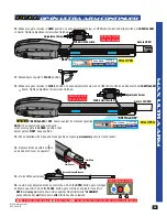
Position gate half-way open and STOP gate.
This gate position will put the most amount of
resistance on the ERD sensor when gate cycles.
STOP Gate
Half-way
CLOSE gate. If ERD sensor triggers, reduce
sensitivity. If sensor does NOT trigger,
sensitivity is set correctly.
CLOSE Gate
1
2
TIP: While Adjusting ERD. . . . .
Summary of Contents for MAX ARM
Page 2: ......

