background image

45

MAX Arm/Ultra Arm V1b

CLOSING Direction

Photocell (Reflector)

NORMALLY CLOSED (NC)

Wiring to E3K Photocell

UL325 - 2016 Compliance

UL325 - 2018 Compliance

IMPORTANT:

Photocell MUST be powered by 

12VDC OUT


MONITORED 

or it 

will 

NOT

 be 

MONITORED

.

IMPORTANT:


Photocell 

MUST 

be in alignment 

with reflector or fault 

will occur.

4 5 6

C-1

C-2

NO1

NC1 NC2 NO2

LIGHT ON

SENSITIVITY

Min

Max

DARK ON

Power

Set switch to

“LIGHT ON”

24 to 240 VAC

24 to 240 VDC

1

Com

2

NO

3

NC

Sensitivity Adjustment:

If the photocell does not respond to an 

obstruction, lower the sensitivity by 

turning adjustment counter-clockwise.

12VDC OUT Monitored

OK to 

use

12VDC

PHOTO CLS NC

GND

NOTE:

 To meet the UL 325 2016 standard, 

Type B1 Non-Contact sensor entrapment 

protection device 

MUST

 be 

MONITORED


by the gate operator.

NOTE:


DO NOT use 10K Resistor included with photocell.

Installation Steps:

1. 

Set switch to “LIGHT ON”

2. 

Wire 12V power to photocell

3. 

Wire 

PHOTO CLS NC


  to photocell 

NO1

  Wire 

GND

 to photocell 

C-1

4. 

Align photocell to reflector

5. 

Adjust sensitivity

DO NOT

 connect

to NC1 #3.

OPEN ONLY 

NC

OPEN ONLY 

10K

PHOTO CLS 

NC

OPEN/CLS 

NC

GND

12VDC OUT

GND

CLS ONLY   

10K

OPEN/CLS 

10K

12VDC OUT

UL SENSOR N.C.

UL SENSOR 10K

P

NSOR N.C

P

NSOR N.C

P

SOR N.

P

SOR N

SOR N

SOR N

OR N

OR N

OR 

Polarity does 

NOT

 matter

CLOSING Direction

Photocell (Reflector)

NORMALLY CLOSED (NC)

Wiring to E3K Photocell

IMPORTANT:

Photocell MUST be powered by 

12VDC OUT


MONITORED 

or it 

will 

NOT

 be 

MONITORED

.

IMPORTANT:


Photocell 

MUST 

be in alignment 

with reflector or fault 

will occur.

4

5 6

C-1

C-2

NO1 NC1 NC2

NO2

LIGHT ON

SENSITIVITY

Min

Max

DARK ON

Power

Set switch to

“LIGHT ON”

24 to 240 VAC

24 to 240 VDC

1

Com

2

NO

3

NC

Sensitivity Adjustment:

If the photocell does not respond to an 

obstruction, lower the sensitivity by 

turning adjustment counter-clockwise.

12VDC OUT Monitored

OK to 

use

12VDC

PHOTO CLS NC

UL 2018 Label on packaging

GND

Installation Steps:

1. 

Set switch to “LIGHT ON”

2. 

Wire 12V power to photocell

3. 

Wire 

PHOTO CLS NC


  to photocell 

NO2

  Wire 

GND

 to photocell 

C-2

4. 

Align photocell to reflector

5. 

Adjust sensitivity

DO NOT

 connect

to NC2 #4.

OPEN ONLY 

NC

OPEN ONLY 

10K

PHOTO CLS 

NC

OPEN/CLS 

NC

GND

12VDC OUT

GND

CLS ONLY   

10K

OPEN/CLS 

10K

12VDC OUT

UL SENSOR N.C.

UL SENSOR 10K

P

NSOR N.C

P

NSOR N.C

P

SOR N.

P

SOR N

SOR N

SOR N

OR N

OR N

OR 

NOTE:

 To meet the UL 325 2018 

standard, Type B1 Non-Contact 

sensor entrapment protection 

device 

MUST

 be 

MONITORED


by the gate operator.

****NEW!!!****

E3K with Built-In Resistor to comply with

UL325-2018 Requirements

** Please consult enclosed wiring diagrams

and operator instruction manual**

For 10K Resistor E3K Photocell wiring see next page

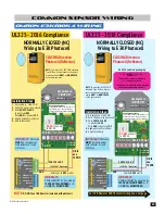
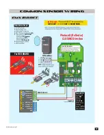
common sensor wiring

OMRON E3K-R10K4 Wiring

r

e

ll

o

rt

n

o

C


m

r

A


P

S

D

r

e

ll

o

rt

n

o

C


m

r

A


P

S

D

Polarity 

DOES 

matter 

Summary of Contents for MAX ARM

Page 1: ...NFORMS TO UL STD 325 UL CLASS I II III IV CERTIFIED TO CAN CSA STD C22 2 NO 247 SAFETY SENSORS REQUIRED Installation and Owners manual for max arm max ultra arm Actuator Arms M a x A r m M a x u lt r a A r m r m JO G GATE OPEN CLOSE RESET ALARM M a x A r m C o n t r o l B o x V1b 3 ...

Page 2: ......

Page 3: ...s Miller R Band Wireless iGaze RE Kit Wireless 45 46 47 48 49 50 51 52 53 gate safety and requirements Important Gate Construction Information General Requirements UL 325 Compliant Installation Requirements Important Safety Imformation UL 325 Model Classifications Gate Safety Installation Intended Use of Swing Gate Operator 4 4 4 5 6 7 8 9 10 11 1 1a 1b Mount Control Box AC Input Power ONLY Gound C...

Page 4: ...y back up cycles 7 Amp Hr batteries fully charged Approx 500 cycles Entrapment protection UL 325 Type A Inherent ERD sensor Inputs for NORMALLY CLOSED N C or 10K Type UL 325 Type B1 photo cell and Type B2 sensing edge MONITORED when used solar powered control box 13 5 343 mm 5 75 146 mm 17 432 mm JOG GATE OPEN CLOSE RESET ALARM 24V SOLAR BATTERY LIGHT SAFETY CENTER EXIT J3 J2 J4 J5 30 A 30 A 30 Am...

Page 5: ... W Maximum input power 6 A Operating Temperatures 20 C 50 C 4 5 Max 59 25 39 8ft 12ft 16ft 18ft Max Weight Length 1600 lbs 1200 lbs 800 lbs 600 lbs Min 40 25 Power supply 24 VDC Max Stroke length 21 2 in Nominal thrust 5500 N Maximum operating current 6A Operating Temperatures 4 F 122 F 20 C 50 C Max 59 25 39 7 35 186mm 5 07 128mm 5 127mm 8ft 12ft 16ft 18ft Max Gate Weight Length 1600 lbs 725 kg 1...

Page 6: ...less above grade shall be guarded or covered All openings shall be designed guarded or screened from the bottom of the gate to the top of the gate or a minimum of 72 in 1 83 m above grade whichever is less to prevent a 2 1 4 in 57 mm diameter sphere from passing through the openings anywhere in the gate and in that portion of the adjacent fence that the gate covers in the open position The gate pa...

Page 7: ...a barrière doit être installée dans un endroit où la barrière et les structures avoisinantes sont suffisamment éloignées l une de l autre Les barriers battantes ne doivent pas ouvrir dans une zone d accès public d The gate must be properly installed and work freely in both directions prior to the installation of the gate operator Do not over tighten the operator clutch or pressure relief valve to ...

Page 8: ... situé où il existe un risque de coincement ou d obstruction comme sur le bord d ouverture sur le bord de fermeture et sur les poteaux montés sur l intérieur ou l extérieur d une barrière coulissante pour véhicules 2 One or more contact sensors shall be located at the bottom edge of a vehicular vertical lift gate 2 Au moins un capteur de contact doit être situé sur le bord inférieur d une barrière...

Page 9: ...n increase the risk of injury or death 4 Vérifiez le fonctionnement de l ouvre barrière une fois par mois Le sens de la course DOIT s inverser lorsque la barrière entre en contact avec un objet dur ou la barrière DOIT s arrêter lorsqu un objet active les capteurs sans contact Vérifiez à nouveau l ouvre barrière après tout réglage de la force de déclenchement ou du seuil de fin de course Un réglage...

Page 10: ...security personnel SECURITY AUTHORIZED PERSONNEL ONLY ul 325 model classifications A Inherent entrapment protection system B1 Provision for connection of a non contact sensor photoelectric sensor or the equivalent B2 Provision for connection of a contact sensor edge device or the equivalent C Inherent adjustable clutch or pressure relief device D Provision for connection of an actuating device req...

Page 11: ...ding 0 50 inches If distance is greater than 4 inches for this area then entrapment protection is required If distance is less than 16 inches entrapment protection is required in this area With the hinge mounted on the corner of the pilaster the entrapment area is eliminated and protection is NOT needed for this area Gate Closed Gate Opened 4 to 16 DO NOT install operator upside down DO NOT instal...

Page 12: ...GNS shall be installed One on EACH side of the gate area where easily visible Moving Gate Can Cause Serious Injury or Death KEEP CLEAR Gate may move at any time without prior warning Do not let children operate the gate or play in the gate area This entrance is for vehicles only Pedestrians must use separate entrance Install on back side DO NOT install a opening device accessible through the gate ...

Page 13: ...c e is for ve hic les on ly Pe de str ian s mus t us e se pa rate en tra nc e M ovin g Gate Can Cause Serious In ju ry or Death KE EP CL EA R Ga te may mov e at an y tim e withou t prior wa rning Do no t let ch ild ren op erate the ga te or pla y in the ga te area Th is en tra nc e is for ve hic les on ly Pe de str ian s mus t us e se pa rate en tra nc e intended use of swing gate operator The ope...

Page 14: ...ator for Step 1 1a 1b max arm max ultra arm Page 12 14 Page 15 17 1a mount max arm brackets release drive rod Insert key and turn 90 Lift key plate Drive rod can now be pulled out Drive Rod 1 2 Hardware Not Supplied Front Bracket Bolt or weld to gate Bolt or weld to secure Rear Bracket Assembly Sleeve Anchors Not Supplied Use a nail to remove rear pin Rear Pin Locknut For PUSH open installation pl...

Page 15: ...open the gate PULL OPEN or PUSH OPEN Installation See next page See the GATE SAFETY and REQUIREMENTS in front of this manual pages 4 11 for mounting requirements and limitations Temporarily mount arm in desired position determined by next page s dimensions Manually swing gate to the OPEN and CLOSE positions When satisfied with gate positions permanently mount brackets making sure that arm is LEVEL...

Page 16: ...FIRST Install overlap maglock accordingly to account for this When A and B are similar dimensions smoother gate operation and reduce motor strain occurs Option 1 allows fastest opening closing time B dimension being MINIMUM allowed NOTE Rear bracket MUST be fabricated 2 5 2 5 pull open dimensions push open dimensions 41 Min C1 C1 41 Min Option 1 9 Option 2 10 Option 3 11 Minimum distance needed fo...

Page 17: ...e Locknut brackets Insert key and turn 90 Lift key plate Drive rod can now be pulled out release drive rod Rear Pin Drive Rod PULL Open Rear Bracket PUSH Open Rear Bracket Arm Connection The bracket MUST be level and VERY secure to the plate and wall Extreme force will be exerted on this bracket during gate cycling For PUSH open installation please order MX115 MX115 Bracket Plate Weld completely a...

Page 18: ...standing or flowing water This will damage the operator Arm MUST be level IMPORTANT Drive rod MUST NOT be FULLY extended when installed This will damage the arm Rotate fully extended rod back at least two full turns BEFORE installing the arm in extended position Rotate rod back 2 turns min Release the drive rod and fully extend Drive Rod Extension If brackets are going to be welded to the gate and...

Page 19: ...ar dimensions smoother gate operation and reduce motor strain occurs Option 1 allows fastest opening closing time B dimensions being min allowed NOTE Rear bracket MUST be fabricated 2 5 2 5 pull open dimensions push open dimensions 40 25 Min C1 C1 40 25 Min Minimum distance needed for clearance A B 59 25 59 25 59 25 C 8ft 12ft 16ft 18ft Max Gate Weight Length 1600 lbs 725 kg 1200 lbs 544 kg 800 lb...

Page 20: ...lp with re installation Couplings and conduit not provided Use flexible conduit to connect to control box not provided EXIT PWR ALARM POWER SOLAR IN BATTERY INPUT OPENING CLOSING MOTOR 2 MOTOR 1 ERD OBD PORT BLACK BOX PROGRAMMING SOLAR MODE MOTOR OVER LOAD ERD MOTOR OVER LOAD MIN MAX OFF MAX SENSE MAX SENSE BATTERY BACKUP MODE ERD SENSITIVITY MOTION CONTROL OPEN CLOSING GATE SPEED MOTOR 2 LIMITS M...

Page 21: ...ingle Phase 230VAC Only 230VAC 230V Set to 230V Power Terminal IMPORTANT Make sure there are NO exposed bare wires at the power terminal connection 115 OR 230VAC Input AC Power Wire CAUTION Make sure circuit breaker is OFF from incoming AC input wire BEFORE wiring CAUTION If input AC power selector switch is set for 115V but input power is actually 230 V 7 Amp Fuse will blow 7A FUSE POWER On Off W...

Page 22: ...ROTECTION in lightning prone areas To be effective ground connections should be made with a minimum 12 AWG 600 volt insulated wire to a ground point within 10 feet of the control box The ground point must be at an electrical panel a metallic cold water pipe that runs in the earth or a grounding rod Chassis Ground Grounding Rod MOTOR 2 ERD MOTOR OVER LOAD MIN MAX OFF OL PEED MOTOR 2 LIMITS MAG LOCK...

Page 23: ... POWER ANTI LGATE ON M 3 1 TROL SE L CLOSING MAX NSE B BACK ENSITIVITY PLACE TTERY LEAV CLOSE LEAVE OPEN Y VOLTAGE F 2 16 MIN 3 1 14 7 M CONTRO ONTROL LOOP PWR D GNAL 2VDC OUTPUT GND Gate Set the desired opening direction See the illustration and next pages ID Plug Error If ID plug is NOT plugged in board will constantly beep and arm will NOT function Operator Set operator to SINGLE for a single a...

Page 24: ...ol box memory Press and HOLD STOP and CLOSE buttons together for 5 sec until BEEP ALARM is heard Screen will display LEARNING LIMITS 10 Manually move gate to CLOSE position BEEP ALARM BEEP ALARM REAR bracket secured 8 With operator shaft in same position temporarily mount FRONT bracket Clamp or tack weld to gate in the OPEN position MOTION CONTROL OPEN STOP CLOSE LEARNING LIMITS 9 Make sure gate r...

Page 25: ...5 5 typical as shown This will be CLOSE position of operator 6 Bolt FRONT bracket to operator 7 Manually move gate to CLOSE position 1 Clear limits from control box memory Press and HOLD STOP and CLOSE buttons together for 5 sec until BEEP ALARM is heard Screen will display LEARNING LIMITS 9 Make sure gate remains in CLOSE position Loosen CLOSE limit knob and slide until BEEP ALARM is heard Tighte...

Page 26: ...haft to 5 5 typical as shown This will be OPEN position of operator 4 Retract shaft until a BEEP ALARM is heard from control box 3 Manually release actuator arm See page 15 Limit Switch Limit Switch Max 60 3 39 1531 mm 10 mm 7 35 186mm 5 07 128mm 5 127mm 2 MAX Ultra Arm V1 Limit Switch Limit Switch PULL OPEN CLOSE LIMIT ADJUSTMENT OPEN LIMIT ADJUSTMENT PUSH OPEN PULL OPEN OPEN LIMIT ADJUSTMENT CLO...

Page 27: ...sting Limits See note below Adjusting Limits See note below Re lock Manual Release Adjustment Screw OPEN Limit Switch Gate is OPEN Gate is CLOSED Adjustment Screw CLOSE Limit Switch BEEP ALARM 11 Manually move gate to CLOSE position Close NOTE If 2 consecutive beeps are heard when moving gate to CLOSED position then adjust gate to FIRST beep position PULL OPEN OPEN LIMIT ADJUSTMENT CLOSE LIMIT ADJ...

Page 28: ...ith operator shaft in same position temporarily mount FRONT bracket Clamp or tack weld to gate in the CLOSE position 9 Remove limit cap with 2 screws and slide limit cover off operator Rear bracket already secured to gate post REAR bracket secured CLOSE position 5 5 Extend Manual Release Manual Release Retract BEEP See page 15 Bolt on FRONT bracket Continued on next page 7 Manually move gate to CL...

Page 29: ...box memory see 1 above Adjusting Limits See note below Adjusting Limits See note below Re lock Manual Release Adjustment Screw CLOSE Limit Switch Gate is CLOSED Gate is OPEN Adjustment Screw OPEN Limit Switch BEEP Open NOTE If 2 consecutive beeps are heard when moving gate to OPEN position then adjust gate to FIRST beep position PULL OPEN OPEN LIMIT ADJUSTMENT CLOSE LIMIT ADJUSTMENT PUSH OPEN Max ...

Page 30: ... Contact Edge Sensor list of Sensors UL325 2018 Wireless Module Beam Height 21 Normal 27 5 Max Beam 5 or LESS from CLOSED gate CLOSING direction Photocell Entrapment Area Entrapment Area Gate Open Gate Open Entrapment Protection 10K Sensing Edge Install along entire edge of gate The hinge area may need protection against entrapment MAX 10K mini sensing edge works well in this area OPEN CLOSE direc...

Page 31: ...factory default Power Power test photo cls nc sensor Test PHOTO CLS NC entrapment protection sensor Photocell typically used 1 Press and HOLD the STOP button then the OPEN button together until beeping is heard learn mode begins NOTE DO NOT press the OPEN button before the STOP button or learn mode will NOT function 3 Press STOP button again within 5 min to end learn mode beeping stops NOTE If STO...

Page 32: ...OTION CONTROL OPEN STOP CLOSE Adjust ERD for EACH direction In Ground Loops Loop Detector Rack Safety loops wired in series Center Loop Safety Loop Safety Loop Exit Loop Plug In Loop Detectors EDI Loop Detector ON 1 2 3 4 5 6 7 8 5 Op tim um Se ns Increa se Se ns De crea se Se ns DE FL EC TO METER PO WER ON No rm al Po we r OF F No Po we r LE D INDICA TO RS DE TE CT ON De tect OF F No De tect 2 Hz...

Page 33: ... preventing UNAUTHORIZED entry Gate Speed Typically Set to MAX Maglock Delay Set to OFF Turned OFF NO Maglock installed Set to 1 5 sec or 2 5 sec You MUST select a time delay when using a maglock Maglock power disengages 1 5 sec or 2 5 sec before gate starts opening Dual Gate Operators using Maglock Primary gate opens FIRST so install maglock accordingly MAGLOCK LED Monitors Maglock ON Locked OFF ...

Page 34: ... OPEN ONLY NC OPEN ONLY 10K PHOTO CLS NC OPEN CLS NC GND 12VDC OUT GND CLS ONLY 10K OPEN CLS 10K 12VDC OUT UL SENSOR N C UL SENSOR 10K O R N C O R N C O R N C O R N C O N C N C N C N C C SENSOR SENSO SENSO SENSO SENSO ENSO ENS ENS NS O R 10K O R 10K O R 10K O R 10K O 10K 10K 10 10 1 C NSOR R R R R R 1 1 1 SOR C R R R R R R 1 SO O R R R R R R R R SO O O R R R R R R R SO O O O R R R R R R SO O O O O...

Page 35: ...WER REPLACE BATTERY LEAVE CLOSED LEAVE OPEN OPEN 1 TIME BATTERY VOLTAGE E F 1 2 RESET ID PLUG MODULE PORT GATE OPEN GND OPEN ONLY NC OPEN ONLY 10K PHOTO CLS NC OPEN CLS NC GND 12VDC OUT GND GND GND GND GND JOG CLOSE JOG OPEN TAMPER IN TAMPER NO GATE DISABLE KEYPAD CARD GND GND MAX OPEN FIRE DEPT RADIO GND RADIO SIGNAL STRIKE CLOSE COM COM STOP OPEN CLS ONLY 10K OPEN CLS 10K 12VDC OUT NO COM NC GAT...

Page 36: ...T 2 LIMIT 1 LIMIT 2 ID PLUG ERROR 24VDC OUTPUT 12VDC OUTPUT GND GND LOOP SAFETY OFF SINGLE OPEN ON OFF BATTERY CLOSE DUAL ON ANTI TAILGATE PUSH OPEN PULL OPEN GATE OFF 1 2 3 4 5 6 7 8 9 10 OFF 1 5 6 MIN MIN MAX ON OFF 2 5 sec 1 5 sec FAULTS OPERATOR DSP ARM CONTROLLER OFF LOOP 16 MIN 16 MIN 3 1 14 12 9 7 3 1 14 12 9 7 UL SENSOR 10K UL SENSOR N C MODE A MODE B MOTOR 1 INPUTS MOTOR 2 INPUTS MAXIMUM ...

Page 37: ...PORT GATE OPEN GND OPEN ONLY NC OPEN ONLY 10K PHOTO CLS NC OPEN CLS NC GND 12VDC OUT GND GND GND GND GND JOG CLOSE JOG OPEN TAMPER IN TAMPER NO GATE DISABLE KEYPAD CARD GND GND MAX OPEN FIRE DEPT RADIO GND RADIO SIGNAL STRIKE CLOSE COM COM STOP OPEN CLS ONLY 10K OPEN CLS 10K 12VDC OUT NO COM NC COM GATE CLOSED LIMIT 1 GND LIMIT 2 MOTOR 1 LIMITS MOTOR 1 MOTOR 2 LIMIT 1 GND LIMIT 2 LIMIT 1 LIMIT 2 L...

Page 38: ... The gates will not have any play in CLOSED position they are locked in place Single Gate Secondary gate must have a positive stop such as a trim piece on the SECONDARY gate that overlaps primary gate Secondary gate reaches close position FIRST Mode B DIP Switch 3 MUST be ON The MAGLOCK DELAY must be set to 1 5 sec so the gates do not collide due to the positive stop overlap plate Dual Gates Close...

Page 39: ... MOTOR 1 ERD OBD PORT BLACK BOX PROGRAMMING SOLAR MODE MOTOR OVER LOAD ERD MOTOR OVER LOAD MIN MAX OFF MAX SENSE MAX SENSE BATTERY BACKUP MODE ERD SENSITIVITY MOTION CONTROL OPEN CLOSING GATE SPEED MOTOR 2 LIMITS MAG LOCK UL ENTRAP STOP CLOSE CLOSE TIMER MAGLOCK DELAY JOG BATTERY TEST BATTERY INPUT ERROR BATTERY IN USE POWER REPLACE BATTERY LEAVE CLOSED LEAVE OPEN OPEN 1 TIME BATTERY VOLTAGE E F 1...

Page 40: ...or solar mode Control Panel Solar Regulator 24V 10A Morning Star 24V Solar Panel Output 36V max Open Circuit Wire solar panel terminals to solar regulator input Caution polarity matters Solar Panel P S N 1 2 3 4 Insert the included fuse into the empty fuse slot no polarity Turned ON the switch located directly underneath the fuses Leave the solar mode switch off and follow the included installatio...

Page 41: ...shes 25 change of Inductance Both LED s Flashing CurrentLoop Fault PW R LED Flashing Previous Loop Fault EDI Tel 480 968 6407 DEFLECTO METER SENS RESET POWER DETECT EDI SENS LMA1800 LP OPTIONS 1 2 3 4 5 6 7 8 O N EDI LMA1800 LP NOTE While in low power mode EXIT LOOP detector remains ON CENTER SAFETY LOOP detectors are turned OFF Power radio receiver using 12V DC OUTPUT In low power mode 12V DC OUT...

Page 42: ...Total System Current Draw mA Cycles day w 1 rainy day Cycles day w 10 rainy days Cycles day w 1 rainy day Cycles day w 10 rainy days Cycles day w 1 rainy day Cycles day w 10 rainy days 60 W 26 1328 346 1233 252 1138 157 50 1295 314 1197 215 1098 117 100 1227 245 1121 139 1015 33 200 1091 109 970 12 848 133 250 1023 41 894 88 765 217 85 W 26 1442 460 1309 327 1176 195 50 1409 427 1273 291 1136 155 ...

Page 43: ...021 10 58 53 INFO SEC_MC Fully Open Posi on Learned Fri 07 11 2021 10 57 40 INFO PRI_CIO Communica on Established Fri 07 11 2021 10 57 38 ENTRAP PRI_MC Photo Cell Deac vated Fri 07 11 2021 10 57 34 ENTRAP PRI_MC Photo Cell Ac vated Fri 07 11 2021 10 57 21 INFO Radio Input Deac vated Fri 07 11 2021 10 57 21 INFO Radio Input Ac vated Fri 07 11 2021 10 56 46 WARNING PRI_MC Tamper Reported Fri 07 11 2...

Page 44: ...N 1 TIME then if AC power is lost gate will automatically open 1 time If CLOSE TIMER is OFF then gate will not close automatically A close command radio close is required to close gate Loop detector is defective CENTER EXIT or SAFETY All 3 loop LEDs flashing indicates loop fault Loop has a short or open Measure loop resistance Check if manual release on arm is released If so re lock manual release...

Page 45: ...N OFF switch is ON If so check AC power Battery needs to be replaced if BATTERY TEST fails and REPLACE BATTERY LED is ON Battery not plugged in to BATTERY INPUT port An entrapment event has occurred check if an entrapment sensor was triggered see if PHOTO CLS OPEN ONLY or OPEN CLS LEDs are on An ERD event may have occurred Check for gate obstruction ERD sensitivity is too high for application Re a...

Page 46: ...p Detector might be defective Replace defective loop detector NOTE RENO loop detector LED s flash as default but function normally ignore the flashing Loop fault condition check if SAFETY loop wires are connected into to loop input connector properly Check if SAFETY loops are wired in series Check if loop detector is inserted properly in Loop Rack slot Set unique loop detector frequency for each l...

Page 47: ...CLOSING Direction Photocell Reflector NORMALLY CLOSED NC Wiring to E3K Photocell IMPORTANT Photocell MUST be powered by 12VDC OUT MONITORED or it will NOT be MONITORED IMPORTANT Photocell MUST be in alignment with reflector or fault will occur 4 5 6 C 1 C 2 NO1 NC1NC2NO2 LIGHT ON SENSITIVITY Min Max DARK ON Power Set switch to LIGHT ON 24 to 240 VAC 24 to 240 VDC 1 Com 2 NO 3 NC Sensitivity Adjustm...

Page 48: ... NC to photocell NO1 Wire GND to photocell C 1 4 Align photocell to reflector 5 Adjust sensitivity DO NOT connect to NC1 3 OPEN ONLY NC OPEN ONLY 10K PHOTO CLS NC OPEN CLS NC GND 12VDC OUT GND CLS ONLY 10K OPEN CLS 10K 12VDC OUT UL SENSOR N C UL SENSOR 10K O C OR 10K O OR 10K O OR 10K O OR 10K O OR 10K R 10K R 10K R 10 R 10 Polarity does NOT matter UL 2018 Label on packaging NOTE To meet the UL 32...

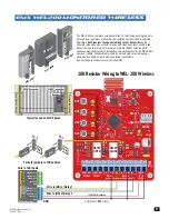
Page 49: ...T matter 10K JP 1 Jumper 10K JP 2 Jumper 10K Resistor Wiring to WEL 200 Wireless EMX WEL 200 monitored WIRELESS WEL 200R Wireless Edge link WEL 200T Wireless Edge link WEL 200T Wireless Edge link CLOSE Transmitter OPEN Transmitter Receiver WEL 200T WEL 200T WEL 200R The WEL 200 is a complete wireless solution for interfacing sensing edges to gate and door operators while ensuring compliance with U...

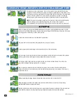
Page 50: ...havior double check the edge wiring termination and transmitter batteries CONNECTING RECEIVER TO TRANSMITTER O N 1 2 3 4 MODE OPEN CLOSE WEL 200T Wireless Edge link SW1 LED 3 CH1 LLD1 CH1 LLD1 CH1 steps testing Set each channel to the desired OPEN CLOSE direction function using the MODE dip switch If a DIP switch is in the OPEN ON position then that channel will trigger the OPEN relay on receiver ...

Page 51: ...NOTE If photocell does NOT function using VRX power input connect power to VTX input instead emx irb ret OPEN ONLY NC OPEN ONLY 10K PHOTO CLS NC OPEN CLS NC GND 12VDC OUT GND CLS ONLY 10K OPEN CLS 10K 12VDC OUT UL SENSOR N C UL SENSOR 10K NSOR N C P NSOR N C P SOR N P SOR N P SOR N SOR N OR N OR N OR IMPORTANT Photocell MUST be powered by 12VDC OUT or it will NOT be MONITORED DSP Arm Controller 43...

Page 52: ...perator Installation Steps 1 Set DIP switches on receiver 2 Install jumper on receiver 3 Wire DSP 12VDC OUT power to receiver 4 Wire PHOTO CLS NC to receiver photocell NC Wire DSP Board GND to receiver photocell COM 5 Wire 12V DSP power to transmitter 6 Align photocells 7 Adjust sensitivity on receiver DIP switches 1 2 4 are OFF Switch 3 is ON If trouble occurs try turning switch 4 OFF NOTE Power ...

Page 53: ...ed Sensitivity Adjustment If the IRB MON does not respond to an obstruction lower the sensitivity by turning adjustment counter clockwise Transmitter TX Receiver RX Normally Closed PHOTO CLS NC Common GND Green LED Green LED NOComNC Jumper TX RX NOTE To meet the UL 325 2018 standard Type B1 Non Contact sensor entrapment protection device MUST be MONITORED by the gate operator Installation Steps 1 ...

Page 54: ...LOOP 16 MIN 16 MIN 3 1 14 12 9 7 3 1 14 12 9 7 UL SENSOR 10K UL SENSOR N C MODE A MODE B PROGRAM MOTOR 1 INPUTS MOTOR 2 INPUTS MAXIMUM CONTROLS DSP ARM CONTROLLER MIN AP AGLOCK ELAY JOG EN ON O BATTE CL 2 5 s sec RM CO PO SO BA I MO OPEN D POR ACK B OGRA S ERY ST RE B AGE F O 4 12 P DIP Switches 1 ON 2 OFF 3 ON 4 ON Pos Neg CS1 C1 CS2 C2 A RBAND transmitter is needed for each channel of the receiv...

Page 55: ... P ARM CONTROL 1 OFF 2 OFF 3 OFF 4 OFF 5 ON 6 ON Both safety edges are 10KΩ resistive Pos Neg NO1 C1 C2 NO2 Can be mounted on Gate s OPENING OR CLOSING position Can be mounted on Gate s OPENING OR CLOSING position Frequency DIP switches 2 3 MUST be set the same as the receiver DIP switches 3 4 Wire 10K Edges TCOO900 Transmitter RCOO900 Receiver OPEN ONLY NC OPEN ONLY 10K PHOTO CLS NC OPEN CLS NC G...

Page 56: ...7 8 5 Op tim um Sen s Inc rea se Sen s De cre ase Sen s DE FL EC TO ME TE R PO WE R ON No rm al Pow er OF F No Pow er LE D IND ICA TO RS DE TEC T ON De tec t OF F No De tec t 2 Hz Fla sh Del ay Tim ing SW 1 SW 2 Fre que ncy ON ON Low ON OF F Me diu m Low OF F ON Me diu m Hig h OF F OF F Hig h SW 4 SW 5 Ou tpu t B ON ON Pul se on Ent ry ON OF F B sam e as A OF F ON Pul se on Exi t OF F OF F Loo p F...

Page 57: ...sing gate OWNER of the gate operator is responsible for the KEY availability WARNING WARNING NEVER grasp the arm to move gate ALWAYS grasp gate to move it max arm max ultra arm 1 2 2 Insert key and turn 90 1 Insert key and turn 90 Lift key plate cover 90 Gate can now be manually moved Lift key plate Gate can now be moved ...

Page 58: ...Linear Gate Operators 40 CONFORMS TO UL STD 325 UL CLASS I II III IV CERTIFIED TO CAN CSA STD C22 2 NO 247 Installation and Owners manual for max arm max ultra arm Actuator Arms M a x A r m M a x u lt r a A r m r m JO G GATE OPEN CLOSE RESET ALARM M a x A r m C o n t r o l B o x SAFETY SENSORS REQUIRED Version 1 V1b 3 ...

Reviews: