32
MAX Arm/Ultra Arm V1
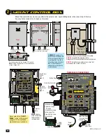
EXIT PWR
ALARM
POWER /
SOLAR IN
BATTERY
INPUT
OPENING
CLOSING
MOTOR 2
MOTOR 1
ERD
OBD PORT
BLACK BOX
PROGRAMMING
SOLAR MODE
MOTOR
OVER
LOAD
ERD
MOTOR
OVER
LOAD
MIN
MAX
OFF
MAX
SENSE
MAX
SENSE
BATTERY
BACKUP MODE
ERD SENSITIVITY
MOTION CONTROL
OPEN
CLOSING GATE SPEED
MOTOR 2
LIMITS
MAG
LOCK
UL
ENTRAP
STOP
CLOSE
CLOSE
TIMER
MAGLOCK
DELAY
JOG
BATTERY
TEST
BATTERY
INPUT
ERROR
BATTERY
IN USE
POWER
REPLACE
BATTERY
LEAVE
CLOSED
LEAVE
OPEN
OPEN
1 TIME
BATTERY VOLTAGE
E
F
1/2
RESET
ID
PLUG
MODULE
PORT
GATE OPEN
GND
OPEN ONLY NC
OPEN ONLY 10K
PHOTO CLS NC
OPEN / CLS NC
GND
12VDC OUT
GND
GND
GND
JOG CLOSE
JOG OPEN
TAMPER IN
TAMPER NO
GATE DISABLE
GND
GND
MAX OPEN
FIRE DEPT
RADIO GND
RADIO SIGNAL
COM
CLS ONLY 10K
OPEN / CLS 10K
12VDC OUT
NO
COM
NC
COM
GATE CLOSED
LIMIT 1
GND
LIMIT 2
MOTOR 1
LIMITS
MOTOR 1
MOTOR 2
LIMIT 1
GND
LIMIT 2
LIMIT 1
LIMIT 2
LIMIT 1
LIMIT 2
ID PLUG
ERROR
24VDC OUTPUT
12VDC OUTPUT
GND
GND
GND
LOOP
LOOP PWR
LOOP
CENTER
SAFETY
OFF
SINGLE
OPEN
ON/OFF
BATTERY
CLOSE
DUAL
ON
ANTI-
TAILGATE
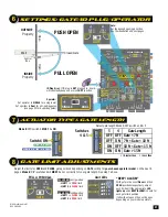
PUSH
OPEN
PULL
OPEN
GATE
OFF
1
2
3
4
5
6
7
8
9
10
OFF
1
2
3
4
5
6
MIN
MIN
MAX
MAX
ON
OFF
2.5 sec
1.5 sec
FAULTS
OPERATOR
DSP ARM CONTROLLER
OFF
EXIT LOOP
16
MIN
16
MIN
3
1
14
12
9
7
3
1
14
12
9
7
UL SENSOR 10K
UL SENSOR N.C.
MODE A
MODE B
PROGRAM
MOTOR 1
INPUTS
[
+
]
[
-
]
[
+
]
[
-
]
MOTOR 2
INPUTS
MAXIMUM CONTROLS
DSP ARM CONTROLLER
15
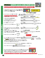
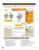
UL sensor learn mode
2. LEDs WILL turn ON for each detected “LEARNED” sensor that has been wired to
the inputs. If a sensor’s LED is NOT on, that sensor has a problem and it MUST be
corrected before continuing.
Possible problems:
•
Photocells are out of alignment
•
Photocells are wired wrong - N.C. or N.O. depending on which type of
photocells are used.
•
Sensor is bad
When all LEDs are ON that should be ON, proceed to next step.
3. Press STOP button again within 5 min. to learn sensors and end learn mode,
beeping stops.
Wired “Learned” Inputs will now be MONITORED.
NOTE: If STOP button is not pressed within 5 min., learn mode terminates. If no
“LEARNED”
sensors are detected then factory default setting is restored (Inputs
will
NOT be Monitored).
MOTION CONTROL
OPEN STOP
CLOSE
MOTION CONTROL
OPEN
STOP
CLOSE
1. Press and HOLD the STOP button & then the OPEN button together until beeping
is heard, learn mode begins. DO NOT press the OPEN button before the STOP button
or learn mode will NOT begin (no beeping).
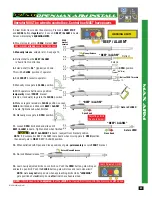
A sensor wired to the PHOTO CLS NC will “AUTOMATICALLY be MONITORED” (Factory default).
All other inputs MUST be learned before they will be monitored.
AUTOMATICALLY MONITORED UL sensor Input
OPEN ONLY
NC
OPEN ONLY
10K
PHOTO CLS
NC
OPEN/CLS
NC
GND
12VDC OUT
GND
CLS ONLY
10K
OPEN/CLS
10K
12VDC OUT
UL SENSOR N.C.
UL SENSOR 10K
O
R N.C.
O
R N.C.
O
R N.C.
O
R N.C.
O
N.C.
N.C.
N.C.
N.C.
.C
SENSOR
SENSO
SENSO
SENSO
SENSO
ENSO
ENS
ENS
NS
O
R
10K
O
R 10K
O
R 10K
O
R 10K
O
10K
10K
10
10
1
C
NSOR
R
R
R
R
R
1
1
1
SOR
C
R
R
R
R
R
R
1
SO
OR
R
R
R
R
R
R
R
SO
O
OR
R
R
R
R
R
R
SO
O
O
OR
R
R
R
R
R
SO
O
O
O
OR
R
R
R
SO
O
O
O
O
OR
R
O
O
O
O
O
O
O
O
O
O
O
L SEN
N
NS
S
S
S
S
S
SO
SO
O
O
L SEN
N
N
NS
S
S
S
S
S
S
L SEN
N
N
N
NS
S
S
S
S
S
L SEN
N
N
N
N
NS
S
S
S
L SE
EN
N
N
N
N
NS
S
S
SE
EN
N
N
N
N
N
N
SE
E
EN
N
N
N
N
SE
E
E
EN
N
N
SE
E
E
E
“Learned” monitored
“Learned” monitored
“Learned” monitored
“Learned” monitored
“Learned” monitored
Automatically monitored
Sensor Learn Mode:
16
dip-switch settings
Set desired features
using DIP-switches.
WR
M
LOOP
P
OFF
SINGLE
DUAL
M
OPERATOR
T LOOP
CLOSING
OBD PORT
BLACK B
MOTOR
OVER
LOAD
MIN
MAX
O
MO
LIMIT 1
3
7
1
2
3
4
5
6
7
8
9
10
OFF
1
2
3
4
5
6
OFF
MODE A
MODE B
Reserved
Battery Beep Mode
2
3
4
5
6
7
8
9
10
Gate in Motion Alert
Strobe Light Relay Control
Quick-Close
Close Tamper Detect
Solenoid OR Maglock
Control Relay
Stop Input Polarity
Open Relay Polarity
UL Closing Photo ON PHOTO
CLS NC Anti-tailgate
OFF
OFF
ON
OFF
ON
OFF
ON
OFF
ON
OFF
ON
OFF
ON
OFF
ON
OFF
ON
ON
1
3
4
&
5
6
Open Relay Pulsed
1
2
MODE B Switches
MODE A Switches
Short Gate < 7 FT - shorter ramp down
Long Gate > 10 FT - longer ramp down
Gate < 7 FT
7 FT < Gate < 10 ft
10 FT < Gate < 13 ft
Gate > 13 FT
MAX Super arm 1300, MAX Super arm 2300
MAX arm, MAX Ultra arm
Secondary
Opposite Direction
Lock on Close
Actuator Type
Select Gate
Length
OFF
ON
OFF
ON
OFF
ON
OFF
ON
5-OFF 4-OFF
5-OFF 4-ON
5-ON 4-OFF
5-ON 4-ON
Open Relay ON when gate open
Open Relay Pulsed when gate open
Secondary moves same as primary
Secondary moves opposite of primary
Stop at close limit (see page 36)
Stop on overload condition after seeing close limit
No beeping when ONLY battery power and gate
is in motion.
Beeping when ONLY battery power and gate is
in motion.
No alarm while gate in motion
Alarm while gate in motion
Tamper Relay NO/C Triggered while gate in motion
for strobe light control.
No quick-close
Quick-close ON
NO close tamper detect
Trigger tamper relay (Alarm for slider ONLY)
Stop Input NO-connect to GND to activate
Stop Input NC-disconnect from GND to activate
Open Relay CLOSED when gate is open
Open relay OPEN when gate is open
For Maglock: Control relay will trigger BEFORE
closed limit is reached.
For Solenoid: Control relay will trigger AFTER
closed limit is reached.
UL Closing Photo anti-tailgate OFF
UL Closing Photo anti-tailgate ON
MUST be OFF
DO NOT turn ON
ON
< = Less Than
> = Greater Than
•
MODE B DIP-switch 6 MUST be ON
Summary of Contents for MAX ARM
Page 2: ......

