TECHNICAL DATA
11 - 4
D-MAXE with OI-TS
www.maxcessintl.com
MI 2-292 1 C
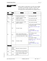
Parallel input matrix
Because of the option for customer-specific programming, there
may be some deviations in the parallel input matrix. Customer-
specific software adjustments of this type are described in the
"Supplementary Operating Instructions" for the D-MAXE system
and are included in the system documentation.
L = Low level (<= 0,9V or blank)
H = High level (3,6V - 24V)
Empty field = not relevant for the specific command
* Inputs 4 and 5 for moving the drive in "Manual" and "Servo
Center" modes
Offset of the guide point (RGPC) in "Automatic" mode
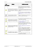
Parallel output matrix
can be used to
adjust the assignment of the logical state (1 or 0) to the
electrical state (active low, active high, high-impedance).
If there are differences compared to the table, they are
described in the "Supplementary Operating Instructions" in the
system documentation.
Mode
Inputs
5
4
3
2
1
0
Locking, external
-
-
-
-
-
H
Automatic
-
-
L
L
H
-
Manual
-
-
L
H
L
-
Servo Center
-
-
H
L
L
-
Move drive left
*
L
H
-
-
-
-
Move drive right
*
H
L
-
-
-
-
RGPC left
*
L
H
-
-
-
-
RGPC right
*
H
L
-
-
-
-
RGPC RESET
*
H
H
-
-
-
-
Status
Outputs
B
*
A
*
LOSS OF NULL (Automatic mode)
-
1
Drive servo-centered (Servo-Center mode)
1
-


