MENUS: 1Y.5 HARDWARE
7 - 11
D-MAXE with OI-TS
www.maxcessintl.com
MI 2-292 1 C
1y.5 Hardware
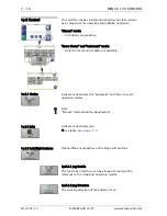
This section contains a description of menus that can be used to
view and set up the properties of the connected input and
output devices.
"Manual" mode:
– All buttons are available.
"Servo-Center" mode:
– All buttons are available.
"Automatic" mode:
– Only selected buttons are available.
1y.5.1 Sensors
The analog sensors present in the system must be calibrated.
Each sensor in the system must be calibrated on the controller
to which the sensor is connected.
1y.5.1.1 Sensor S1 X5/1
...
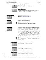
1y.5.1.4 Sensor S4 X9/2 The sensors connected to connections S1 X5/1 to S4 X9/2 can
be calibrated. (On a D-MAXE 3, X9/1 is also connected to X11/
2, and X9/2 is also connected to X11/1 and is referred to as
X11/1 in the menus.)
Note:
It is possible that special sensors are used in the customer's
system, for example a capacitive sensor or a camera. Sensors of
this type cannot be calibrated with the procedure described
here. The information required for a calibration is available in a
set of special operating instructions for the sensor or in
"Supplementary Operating Instructions“ in the system
documentation.
Note:
There can be menus for all sensor connections even if not all the
connections are assigned. Therefore the connections that are
used must be correctly selected.
Additional information may be found in the system diagram of
the system documentation.

