25 Fr
WG2063, 58-8027- 4
Guide de dépannage - soudures
Symptôme
Cause(s) possible(s)
Mesure corrective
Cordon de soudure trop
mince par intervalles.
Cordon de soudure trop
épais par intervalles.
Enfoncements en lambeaux
au bord de la soudure.
Le cordon de soudure ne
pénètre pas le métal
commun.
Le fil crache et se colle.
1. Vitesse de déplacement rapide
ou irrégulière.
2. Réglage de chaleur de sortie
trop bas.
1. Vitesse de déplacement lente
ou irrégulière.
2. Réglage de chaleur de sortie
trop élevé.
1. Vitesse de déplacement trop
rapide.
2. Vitesse de fil trop rapide.
3. Réglage de chaleur de sortie
trop élevé.
1. Vitesse de déplacement
irrégulière.
2. Réglage de chaleur de sortie
trop bas.
3. Manque de/niveau bas de gaz
protecteur.
4. Type de gaz incorrect
(aluminium).
5. Cordon prolongateur trop long.
6. Accumulation possible d’oxydes
sur la surface (aluminium).
1. Fil humide.
2. Vitesse de fil trop rapide.
3. Type de fil incorrect.
4. Manque de/niveau bas de gaz
protecteur.
1. Diminuer et maintenir une vitesse de déplacement
constante.
2. Augmenter le réglage de chaleur de sortie.
1. Augmenter et maintenir une vitesse de déplacement
constante.
2. Diminuer le réglage de chaleur de sortie.
1. Diminuer la vitesse de déplacement.
2. Diminuer la vitesse de fil.
3. Diminuer le réglage de chaleur de sortie.
1. Diminuer et maintenir une vitesse de déplacement
constante.
2. Augmenter le réglage de chaleur de sortie.
3. Utiliser le gaz pour la méthode MIG ou remplir la
bouteille.
4. Utiliser le gaz Argon 100 % seulement.
5. N’utilisez pas un cordon prolongateur de plus que 20 pi
de long.
6. Bien nettoyer la surface avec une brosse métallique
seulement.
1. Utiliser un fil sec et l’entreposer dans un endroit sec.
2. Diminuer la vitesse de fil.
3. Utilisez le fil fourré de flux si vous n’utilisez pas de gaz.
4. Utiliser le gaz pour la méthode MIG ou remplir la
bouteille.
Reassemble spindle cover, spring,
and spindle lock, turning knob 1/4
rotation clockwise to tighten.
4. Hold wire and cut the wire end from
spool.
Do not allow wire to
unravel.
Be sure end of wire is
straight and free of burrs.
5. Pull tension screw down on drive
mechanism. This allows initial
feeding of wire into gun liner by
hand.
6. Lift up swing arm. Feed wire through
feed guide tube, across roller and into
wire liner. Pull down swing arm. Pull up
on wire feed tension screw. Adjust
tension (do not over-tighten). Close
side panel.
7. Remove nozzle by turning counter-
clockwise, then unscrew contact tip
from end of welding torch (See
Figure 4). Plug welder into a proper
power supply receptacle.
8. Turn on welder and set wire speed
4
Wire Feed Arc Welder
Installation
(Continued)
Place welder in an area with at the
least 12” (30.5 cm) of ventilation space
at both the front and rear of unit. Keep
all obstructions out of this ventilation
space.
Store welding wire in a clean, dry
location with low humidity to
prevent oxidation.
Use a properly grounded receptacle
for the welder and ensure welder is
the only load on power supply
circuit. Refer to chart on page 1 for
correct circuit capacity.
Use of an extension cord is not
recommended when using the arc
welder. Voltage drop in the extension
cord may significantly degrade
performance of the welder.
Assembly
BOTTLE RETAINER ASSEMBLY
Attach bottle retainer to welder as
shown (Fig. 2).
WIRE INSTALLATION
NOTE:
Before installing welding wire,
be sure:
a. Diameter of welding wire matches
groove in drive roller on wire feed
mechanism (See Fig. 3). The drive
roller is marked with metric sizes:
.6 mm = .024”
.8 –.9 mm = .030 –.035”
b. Wire matches contact tip in end of
gun. (See Fig. 4).
A mismatch on any item could cause the
wire to slip and bind.
NOTE:
Always maintain control of loose
end of welding wire to prevent
unspooling.
1. Verify unit is off and open door
panel to expose wire feed
mechanism.
2. Remove the spindle lock by pushing
in and rotating 1/4 turn counter-
clockwise. Then remove spring and
spindle cover.
3. Install wire spool onto spindle so
wire will feed from bottom of spool.
Do not cut the wire loose yet.
rate to 10. Activate gun trigger until
wire feeds out 1 1/2” past the torch
end.
Turn welder off
.
9. Carefully slip contact tip over wire
and screw tip into torch end. Install
nozzle by turning clockwise (See
Figure 4). Cut wire off approximately
1/4" from nozzle end.
DUTY-CYCLE THERMAL/OVERLOAD
PROTECTION
The duty-cycle is the percentage of
actual arc welding time that can occur in
a ten minute interval. For example, at a
20% duty-cycle, actual welding can
occur for two minutes, then the welder
must cool for eight minutes.
Internal components of this welder are
protected from overheating with an
automatic thermal switch.
A yellow
lamp is illuminated on the front
panel if the duty-cycle is exceeded
.
Welding operations may continue when
the yellow lamp is no longer illuminated.
POLARITY SELECTION DIAL
A MIG wire requires electrode positive
electrical polarity. A flux-core wire
requires electrode negative electrical
polarity. The welder is factory set for
flux-core wire.
To Change Polarity (See Figure 5a)
NOTE: The arrow on the Polarity Cover
points to the current polarity setting.
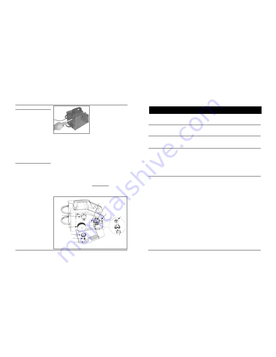
Fig. 2 - Bottle Retainer Assembly
Spindle
Welding wire
spool
Spindle cover
Spring
Spindle lock
Tension screw
Feed guide tube
Swing arm
Drive deck
Roller
support
Roller
Fig. 3 - Weld Wire Routing


