background image

Operation

 29

If you are programming a group 
of fixtures to perform the same 
scenes with synchronized 
master/slave triggering, we 
recommend that you:
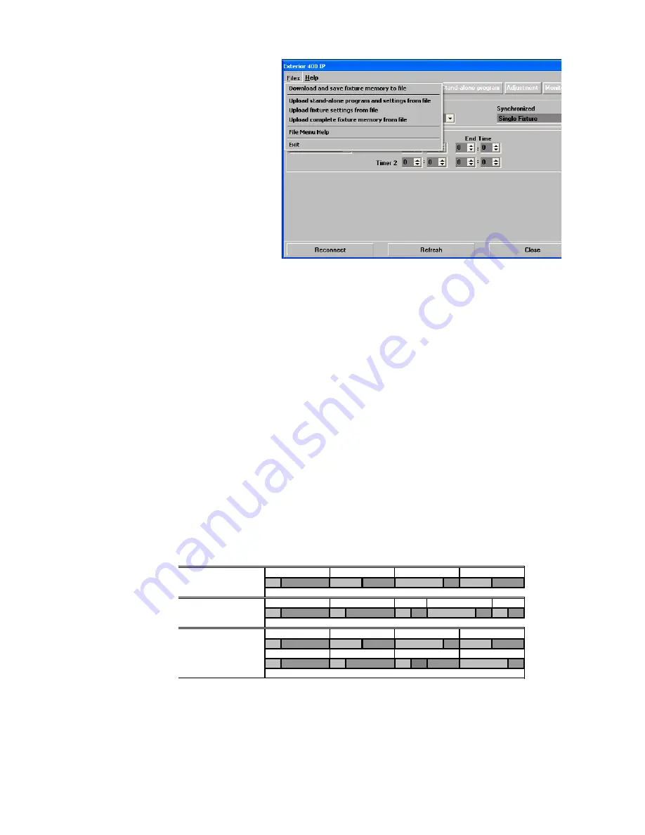
1. Use MUM to program a show 

on one slave fixture

2. Download and save this 

fixture’s memory (program 
and settings) to your PC 
using MUM’s Files menu (see 
Figure 17), and then

3. Upload the program and 

settings to each subsequent 
fixture that you connect to.

For a more detailed explanation 
of synchronized operation and 
how advanced effects can be 
created by programming fixtures 
with a different number of 
scenes, see the next section.

Synchronized stand-alone operation: detailed description

Note:

This section gives advanced information about stand-alone synchronized operation. You only need 
to read it if you require help with problem diagnosis or if you want to program advanced 
synchronized light shows.

The principles in stand-alone synchronized operation are as follows:
1. A scene contains a fade section, followed by a wait section
2. Each fixture can be individually programmed with up to 100 scenes, and each scene can have its own 

individual fade and wait times.

3. Scenes are numbered from 0 to 99.
4. In synchronized operation, one master fixture issues commands to the other slave fixtures to “go to 

scene 

xx

”, where 

xx

 is the scene number that the master will execute next.

5. If a slave has fewer scenes than the master, it will derive which scene to go to by dividing the number of 

the scene it has been commanded to go to (scene 5, for example) by the total number of scenes that the 
slave fixture has (4, for example) in whole numbers (no decimal places). In this example 5 divided by 4 
results in 1, with 1 remainder. This remainder will be the number of the scene that the slave fixture starts 
- scene 1. Generally though, when a Slave fixture reaches its own last scene before the Master fixture, a 
“go to scene x

x

” message will result in the first scene being played.

6. If a slave has more scenes than the master calls, the last scenes in the slave will never be executed, as 

is the case with scene S4 in the following example.

7. In synchronized operation, the wait time is determined by the master. Every slave fixture fades and 

waits at its own rate and then remains in the “wait” state until it receives a “start scene xx” command 
from the master.

8. A slave fixture will not listen for the next message from the master fixture before it has finished its 

current scene. This may result in a slave skipping a scene if the slave has a longer scene time than the 
master. Note that in the following example, the scenes in the slave run out of their programmed 

Figure 17: Managing fixture settings and stand-alone programs 

as files

F=fade, W=wait

Timeline =>
M0

M1

M2

M3

Programmed in Master

F

W

F

W

F

W

F

W

S0

S1

S2

S3

S4

Programmed in Slave

F

W

F

W

F

W

F

W

F

W

Result

M0

M1

M2

M3

F

W

F

W

F

W

F

W

S0

S1

S2

S3

F

W

F

W

F

W

--

-- F

W

Summary of Contents for Exterior 400

Page 1: ...user manual Exterior 400 Image Projector...

Page 2: ...or any other loss occasioned by the use of inability to use or reliance on the information contained in this manual The Martin logo the Martin name and all other trademarks in this document pertaining...

Page 3: ...eapplied deliberately or accidentally before carrying out any installation or maintenance work Disconnect the fixture from AC power before removing or installing any cover or part and when not in use...

Page 4: ...ar optical instruments that may concentrate the light output Ensure that persons are not looking at the LEDs from within 8 3 m 27 3 ft when the product lights up suddenly This can happen when power is...

Page 5: ...orientation 13 Fastening to a surface 13 Tilt adjustment 14 Power and DMX data cable layout 15 AC mains power 16 Connecting to power 16 Control data link 18 Connecting the data link 19 Effects 20 Fixt...

Page 6: ...er supply unit with 100 240 VAC 50 60 Hz operating range Remote configuration and addressing over the DMX data link For the latest photometric data firmware updates documentation product specification...

Page 7: ...void contaminating them with dirt and grease especially from your fingers and follow these precautions 1 Use clean dry lint free gloves when handling optical parts such as filters and gobos 2 To give...

Page 8: ...nt cover B then remove the front cover B and front cover seal C from the fixture housing F 4 Using a T bar or long Allen key reach down into the housing and remove the four effects module retaining sc...

Page 9: ...alled push it away from the color wheel towards the gobo wheel slightly to release it then grasp it by the edges and remove it If your fingers are too large protect the glass with a piece of paper tha...

Page 10: ...LEDs Less reflective side away from LEDs The less reflective side of a coated gobo will absorb less heat if it faces away from the LEDs To determine which side of a gobo is coated hold an object up t...

Page 11: ...ool Push the goboholder in until it snaps into place in its cutout in the gobo wheel Replacing gobos in goboholders Gobos in rotating goboholders are interchangeable and can be replaced with gobos eit...

Page 12: ...e and front cover 1 Lower the effects module into position in the housing Note the number of pins in the multi connectors to the module and reconnect them 2 See Figure 1 on page 8 Using a T bar or lon...

Page 13: ...it in water or any other fluid Do not install it in a location where flooding may occur Ensure sufficient drainage to cope with the heaviest rainfall Make sure that water can drain away from the insta...

Page 14: ...h slots C to secure the fixture Installing bolts through slots C will give approximately 90 of pan adjustment If additional bolts are required to mount the fixture safely install bolts through holes B...

Page 15: ...e opto splitter is required OPTO SPLITTER DMX Universe 1 Universe 1 DMX Universe 2 AC power Fixture Fixture Fixture Figure 8 Schematic cable layout diagram OPTO SPLITTER Power 230V AC 50 Hz Power 230V...

Page 16: ...system at 100 240 V nominal 50 60 Hz Terminal blocks or suitable connection devices must be provided by the installer Danger Lock out power to the entire installation before working on cables and con...

Page 17: ...lug that is suitable for local AC mains power outlets and approved for the installation environment on the supplied power cable If you choose to do this install a grounding type earthed plug that is r...

Page 18: ...cross the data hot and cold conductors of the last fixture on the chain Long parallel runs of AC power and control data cables may cause interference on the data link and must be avoided Even if not r...

Page 19: ...power and data cables may be installed or replaced only by Martin or its authorized service agents The fixture is supplied with a 1 8 meter 5 9 ft data cable tail for data connection The cable contain...

Page 20: ...oothly from 100 to zero Note that four different dimming curves can be selected using the Martin MUM application see Dimming curve options on page 23 or via DMX on the fixture control channel 9 Color...

Page 21: ...Refer to the MUM user manual for instructions on installing and starting the MUM application Connecting a PC with MUM To connect a PC running MUM to an Exterior 400 Image Projector 1 Obtain the Martin...

Page 22: ...controller on a group of DMX channels that are not used by any other device in its DMX universe The DMX address also known as the control address or start channel is the first of these channels Each...

Page 23: ...is disabled to prevent accidental resets 5 Sec A reset command sent on DMX channel 9 must be sent for five seconds to reset the fixture Dimming curve options The Dimming Curve setting provides four di...

Page 24: ...patible with RDM Remote Device Management Using an RDM compliant DMX controller such as the Martin M PC Windows application you can communicate with all the fixtures on a data link via RDM without nee...

Page 25: ...from the effects of low temperature Starting a fixture that is below 0 C 32 F may cause damage to moving parts that is not covered by the product warranty DMX control The industry standard DMX system...

Page 26: ...ur period Enabling stand alone operation To enable stand alone operation set Stand alone operation to Enabled Starting automatically To set stand alone operation to start automatically set Auto progra...

Page 27: ...tton 2 In the Gobo section clicking on a number to select a gobo slot and move the Rotate fader to select rotation direction and speed 3 In the Intensity section move the fader to the desired output i...

Page 28: ...erates in stand alone mode independently of other fixtures Master Sends trigger signals to other fixtures or Synchronized Sets fixture as a slave that receives trigger signals from a master fixture No...

Page 29: ...f a slave has fewer scenes than the master it will derive which scene to go to by dividing the number of the scene it has been commanded to go to scene 5 for example by the total number of scenes that...

Page 30: ...scenes 0 and 2 on the slave are longer than the corresponding scenes on the master M master S slave F fade W wait Time Programmed M0 M1 M2 Master F W F W F W S0 S1 S2 Slave F W F W F W Result M0 M1 M2...

Page 31: ...characteristics are affected by wear and tear after an extended period of use and if you require fixtures to perform within very precise optical and color parameters Cleaning Regular cleaning is esse...

Page 32: ...he current ambient temperature Fan readouts display the current internal and external cooling fan speeds in RPM revolutions per minute Software installation It may be necessary to upload new software...

Page 33: ...dicator LEDs Two LEDs on the rear cover give information about fixture status LED 1 DMX data status Lights steady red if the fixture receives data it cannot recognize Lights steady green when the fixt...

Page 34: ...r Open Strobe 9 fast slow Electronic Sinewave Shutter Open Strobe 10 fast slow Electronic Burst Shutter Open Snap 20 2 0 255 0 100 Intensity fade Zero full Fade 0 3 0 1 15 16 17 31 32 33 47 48 49 63 6...

Page 35: ...o rotation speed on channel 5 CW fast slow CCW slow fast Snap 0 5 0 255 0 125 126 128 129 255 0 100 0 48 49 50 51 100 Gobo indexing and rotation select gobo on channel 4 Indexed position 0 395 Continu...

Page 36: ...ddressing Check fixtures DMX addresses Fixture defective Have faulty fixture serviced by Martin service technician Other device on DMX link defective Bypass devices on DMX link until the faulty device...

Page 37: ...in stand alone mode Optics Light source 7 x Luminus CBT 90 50 W LEDs White LED 6500 K Minimum LED lifetime 60 000 hours to 70 luminous output Manufacturer s figure obtained under manufacturer s test...

Page 38: ...imum ambient temperature Ta max 45 C 113 F Minimum ambient temperature Ta min 30 C 22 F Maximum surface temperature steady state Ta 40 C 65 C 149 F Total heat dissipation calculated 10 1570 BTU hr Pow...

Page 39: ...010 Martin M PC Basic up to 8 DMX universes incl USB Duo interface box P N 90732070 Martin USB Duo USB DMX interface box P N 90703010 Ordering Information Exterior 400 Image Projector Narrow EU model...

Page 40: ......

Page 41: ......

Page 42: ......

Page 43: ......

Page 44: ...www martin com Olof Palmes All 18 8200 Aarhus N Denmark Tel 45 8740 0000 Fax 45 8740 0010...

Reviews: