background image

12

VIDEO CONFIGURATION SUBMENU

Use the Video Configuration submenu to select various video settings such as monochrome mode or blue-only mode.

Monochrome Mode

Use this setting to enable monochrome mode. Only the luminance of the image will be displayed as a grayscale picture.

Blue-Only Mode

Use this setting to enable Blue-Only mode. This mode displays only the blue color component of the image, switching off the red

and green components. Use this mode when calibrating the monitor to SMPTE color bars with the following procedure:

1.

Allow the monitor to warm up for at least 5-10 minutes.

2.

Display SMPTE split-field color bars on the monitor using an external source.

3.

Enable Monochrome mode.

4.

Locate the pluge pattern (super black, black, and gray bars) at the lower-right corner of the screen. Adjust the

Brightness knob until there is no visible difference between the super black and black bars, but the gray bar is still visible.

5.

Adjust the Contrast knob until an even grayscale appears along the top bars.

6.

Disable Monochrome mode.

7.

Enable Blue-Only mode and adjust the Color knob so that the outermost bars (white and blue) appear to match in

brightness.

Video Configuration Submenu

21

OSD Tally

Use this setting to choose how tally is displayed on the screen. The available OSD Tally options depend on the Tally Source
selected in the IMD Configuration submenu (see page 22).

When the Tally Source is set to Standard (contact closure), OSD Tally can be set to Off, RGY, RG, or GR:

Off

On-screen tally is disabled

RGY

Red, yellow, or green tally signals are indicated at both the bottom left and bottom right corners of

the screen. Two or three colors are shown simultaneously by subdividing each tally indicator

RG

Red tally is shown at the bottom left of the screen, and green is shown at the bottom right.

GR

Green tally is shown at the bottom left of the screen, and red is shown at the bottom right.

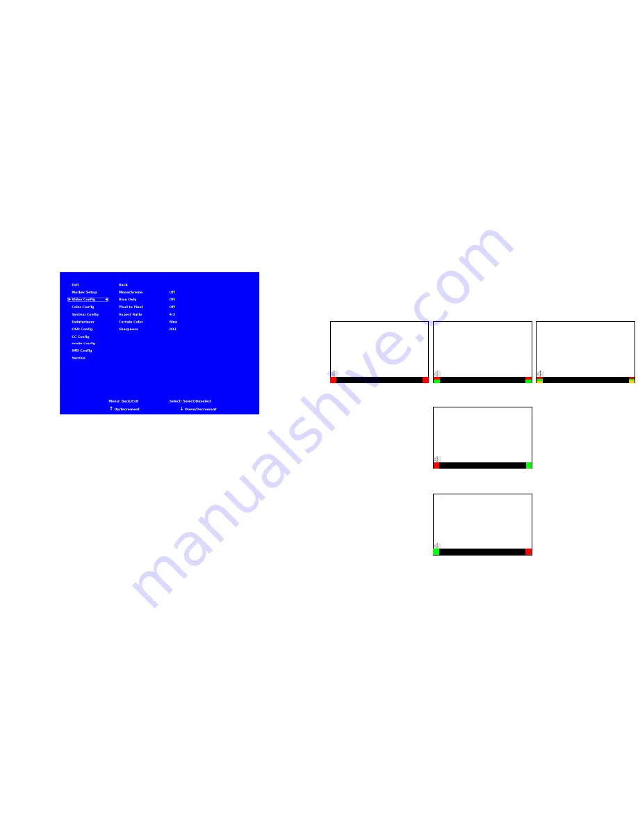
The following diagrams show RGY, RG, and GR OSD Tally modes:

IMD Text

00:00:00:00

RG Mode: both colors activated

(red)

(red)

IMD Text

00:00:00:00

GR Mode: both colors activated

(red)

(red)

IMD Text

00:00:00:00

IMD Text

00:00:00:00

(red)

(red)

IMD Text

00:00:00:00

(red)

(green)

(yellow)

(red)

(green)

(yellow)

RGY mode: single color activated

RGY mode: two colors activated

RGY mode: three colors activated

(red)

(green)

(red)

(green)

Summary of Contents for V-R241-IMD-3G

Page 1: ...o honor the warranty If there is no proof of purchase provided with a warranty claim Marshall Electronics reserves the right not to honor the warranty set forth above Therefore labor and parts may be...

Page 2: ...2 This page intentionally left blank 31...

Page 3: ...he menu buttons 9 Using the RotoMenu knob 9 MARKER SETUP SUBMENU 10 VIDEO CONFIGURATION SUBMENU 12 COLOR CONFIGURATION SUBMENU 15 SYSTEM CONFIGURATION SUBMENU 16 DEINTERLACER SUBMENU 18 OSD CONFIGURAT...

Page 4: ...ut 4 Pin XLR Male Tally Hardware Interface HD 15 Female RS 422 485 Interface 2 x RJ12 Modular 6P6C TALLY GPI HARDWARE INTERFACE HD 15 Activation requires contact closure of pin to ground on the HD 15...

Page 5: ...lowing items are included V R241 IMD 3G Monitor V PS24 6 25 XLR R A DC Power Supply Operating Instructions Inspect the unit for any physical damage that may have occurred during shipping Should there...

Page 6: ...otocols IMD Fixed String Use this setting to display static IMD text on the screen This setting is used to enter IMD text locally when a serial protocol is not used for remote control The IMD Fixed St...

Page 7: ...void serial number conflicts with other Image Video devices on the same serial bus Each name can be up to 16 ASCII characters Press ENTER to edit the IMD Name Use the and buttons to move the cursor Pr...

Page 8: ...Ch Select Use this setting to select which of the 16 possible channels you would like to play on the Left side of the stereo output Right Ch Select Use this setting to select which of the 16 possible...

Page 9: ...menu buttons Press the MENU button to enter the main menu Use the and buttons to scroll through the main menu or each submenu Press the SELECT button to enter a submenu or choose a setting Press the...

Page 10: ...fe Area 88 Safe Area 80 Safe Area 1 85 1 Aspect Ratio 2 35 1 Aspect Ratio 4 3 Aspect Ratio 14 9 Aspect Ratio 13 9 Aspect Ratio 16 9 Marker Examples Marker Setup Submenu OFF No Marker 90 Safe Area 23 C...

Page 11: ...itor menu option to enable or disable the audio presence indicator icon When enabled this icon indicates whether embedded audio is present in the SDI video input A red circle and cross will flash on t...

Page 12: ...lue Only mode and adjust the Color knob so that the outermost bars white and blue appear to match in brightness Video Configuration Submenu 21 OSD Tally Use this setting to choose how tally is display...

Page 13: ...on to switch between several aspect ratio settings As the V R241 IMD 3G monitor has a native resolution of 1366x768 RGB pixels incoming images are automatically scaled to fit the screen In 4 3 mode im...

Page 14: ...s ignored 3 2 only Deinterlacer only recognizes content originating in 24fps and uses 3 2 film mode 25fps content is ignored Film Indicator Use the Film Indicator setting to enable or disable the film...

Page 15: ...ines or weaves each pair of fields into a progressive frame It is normal to see jagged artifacts on fast moving edges Film Mode Film mode uses specialized algorithms to correctly deinterlace content t...

Page 16: ...ing the knob twice Back Exit without making any changes Save Save current settings as defaults Mfg Return to the manufacturer s defaults all settings at 50 Saving and Loading User Presets Use the SAVE...

Reviews: