Marshall Electronics V-R241-IMD-3G Operating Instructions Manual Download Page 11

22

When the Tally Source is set to TSL/MEI 422, OSD Tally can be set to Off or IMD:

Off

On-screen tally is disabled

IMD

Red, yellow, and green tally is displayed according the protocol commands. Green, red, and yellow

colors are shown individually on either the bottom left or right of the screen.

LED Tally

Use this setting to enable or disable the LED Tally. When enabled, the yellow, red and green LEDs above the display will respond
to tally commands, according to the Tally Source setting (see page 23).

Anc. Time Code

Use this setting to enable time code display on the screen. Time code is de-embedded from the vertical ancillary data (VANC)
within the SDI signal. Two types of time code can be selected to display on the screen: LTC (linear time code) or VITC (vertical

interval time code).

The position of the time code display varies based on the aspect ratio setting and presence of IMD text.

Audio Monitor

Use the Audio Monitor menu option to enable or disable the audio presence indicator icon. When enabled, this icon indicates
whether embedded audio is present in the SDI video input. A red circle and cross will flash on the icon if no embedded audio is
present.

Embedded Audio Present

No Embedded Audio

00:00:00:00

Time Code display

Hours

Minutes

Seconds

Frames

11

4:3 Markers

Use this setting to superimpose one of 5 markers on the screen when in 4:3 mode. This setting is disabled when the aspect ratio
is set to 16:9 or Full Screen, and when Pixel-to-Pixel mode is enabled.

Off (No Marker)

95% Safe Area

93% Safe Area

90% Safe Area

88% Safe Area

80% Safe Area

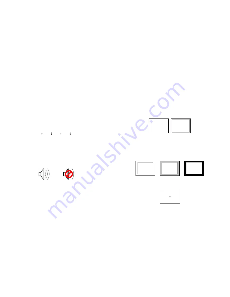
4:3 Marker Examples:

Marker Background

Use this setting to choose how selected markers are displayed on the screen:

Off

The marker is superimposed on the complete image.

50% Gray

Screen area beyond the marker is shown at 50% intensity.

Black

Screen area beyond the marker is shown as black.

Example (80% Marker in 4:3 Mode):

Center Marker

Use this setting to display a center marker on the screen.

Center Marker

Background OFF

50% Gray Background

Black Background

OFF (No Marker)

90% Safe Area

Summary of Contents for V-R241-IMD-3G

Page 1: ...o honor the warranty If there is no proof of purchase provided with a warranty claim Marshall Electronics reserves the right not to honor the warranty set forth above Therefore labor and parts may be...

Page 2: ...2 This page intentionally left blank 31...

Page 3: ...he menu buttons 9 Using the RotoMenu knob 9 MARKER SETUP SUBMENU 10 VIDEO CONFIGURATION SUBMENU 12 COLOR CONFIGURATION SUBMENU 15 SYSTEM CONFIGURATION SUBMENU 16 DEINTERLACER SUBMENU 18 OSD CONFIGURAT...

Page 4: ...ut 4 Pin XLR Male Tally Hardware Interface HD 15 Female RS 422 485 Interface 2 x RJ12 Modular 6P6C TALLY GPI HARDWARE INTERFACE HD 15 Activation requires contact closure of pin to ground on the HD 15...

Page 5: ...lowing items are included V R241 IMD 3G Monitor V PS24 6 25 XLR R A DC Power Supply Operating Instructions Inspect the unit for any physical damage that may have occurred during shipping Should there...

Page 6: ...otocols IMD Fixed String Use this setting to display static IMD text on the screen This setting is used to enter IMD text locally when a serial protocol is not used for remote control The IMD Fixed St...

Page 7: ...void serial number conflicts with other Image Video devices on the same serial bus Each name can be up to 16 ASCII characters Press ENTER to edit the IMD Name Use the and buttons to move the cursor Pr...

Page 8: ...Ch Select Use this setting to select which of the 16 possible channels you would like to play on the Left side of the stereo output Right Ch Select Use this setting to select which of the 16 possible...

Page 9: ...menu buttons Press the MENU button to enter the main menu Use the and buttons to scroll through the main menu or each submenu Press the SELECT button to enter a submenu or choose a setting Press the...

Page 10: ...fe Area 88 Safe Area 80 Safe Area 1 85 1 Aspect Ratio 2 35 1 Aspect Ratio 4 3 Aspect Ratio 14 9 Aspect Ratio 13 9 Aspect Ratio 16 9 Marker Examples Marker Setup Submenu OFF No Marker 90 Safe Area 23 C...

Page 11: ...itor menu option to enable or disable the audio presence indicator icon When enabled this icon indicates whether embedded audio is present in the SDI video input A red circle and cross will flash on t...

Page 12: ...lue Only mode and adjust the Color knob so that the outermost bars white and blue appear to match in brightness Video Configuration Submenu 21 OSD Tally Use this setting to choose how tally is display...

Page 13: ...on to switch between several aspect ratio settings As the V R241 IMD 3G monitor has a native resolution of 1366x768 RGB pixels incoming images are automatically scaled to fit the screen In 4 3 mode im...

Page 14: ...s ignored 3 2 only Deinterlacer only recognizes content originating in 24fps and uses 3 2 film mode 25fps content is ignored Film Indicator Use the Film Indicator setting to enable or disable the film...

Page 15: ...ines or weaves each pair of fields into a progressive frame It is normal to see jagged artifacts on fast moving edges Film Mode Film mode uses specialized algorithms to correctly deinterlace content t...

Page 16: ...ing the knob twice Back Exit without making any changes Save Save current settings as defaults Mfg Return to the manufacturer s defaults all settings at 50 Saving and Loading User Presets Use the SAVE...

Reviews: