28
SERVICE SUBMENU
■
Overview
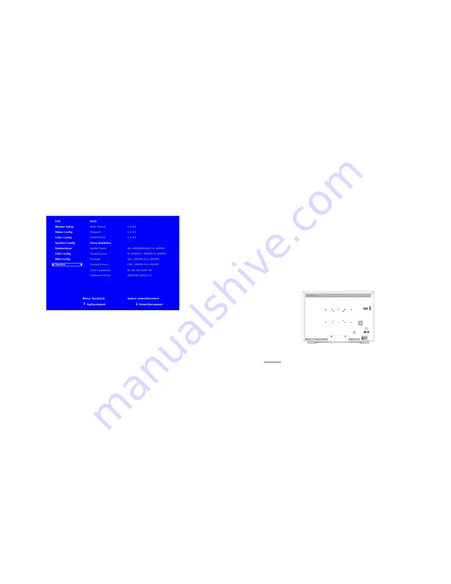
The Service submenu displays the firmware versions of the monitor. Additionally, the status of the serial interface, for
troubleshooting or debugging purposes, can be shown on the screen by highlighting and selecting the Show Statistics text in the
Service Submenu. Contact Marshall Electronics for further information.
The following information is displayed:
• Serial Characters
Rx:
Total number of characters received by the UART
Tx:
Total number of characters transmitted by the UART
• Serial Errors
P:
Number of parity errors
F:
Number of framing errors
O:
Number of FIFO overrun errors
• Packets
Rec:
Number of packets received
Exe:
Packets Executed
• Packet Errors
CRC:
Number of packets that failed CRC check
Err:
Number of other packet errors
• Last Command R:
Last command received
E:
Last command executed
• Software State State:
000:000 1010111 (correct value)
IMD Configuration Submenu
5
Installation and Initial Setup
■
Unpacking
Carefully unpack the V-R241-IMD-3G monitor and verify that the following items are included:
• V-R241-IMD-3G Monitor
• V-PS24-6.25-XLR-R/A DC Power Supply
• Operating Instructions
Inspect the unit for any physical damage that may have occurred during shipping. Should there be any damage, immediately
contact Marshall Electronics at (800) 800-6608. If you are not located within the continental United States, call +1 (310) 333-
0606.
■
Installation
he V-R241-IMD-3G provides VESA standard 75 mm,100 mm and 200 mm mounting holes.
Also, a Desktop Stand is available for this monitor. Please attach the desktop stand according to the image below.
Adequate ventilation is required when mounts or stands are installed to prevent possible damage to the monitor’s internal
components.
Please see the
Dimensions
section for more information.
■
Connections, Power-On and Initial Setup
Plug the DC Power Supply into an AC power source (100-240 V @ 50/60 Hz). Attach the Power connector to the back of the
monitor. Connect the required cables for video signal input and output. (Power must be applied to the V-R241-IMD-3G for the
active loop-though output to be activated.) The monitor defaults to ‘ON’ when power is supplied. Video will automatically be
detected and displayed on the screen.
Desktop Stand Configuration