Marshall Electronics V-R241-IMD-3G Operating Instructions Manual Download Page 14

14

Curtain Color

Use this setting to choose the default color displayed on the screen when no video input is present. Available colors are blue,

red, green, white, and black.

Sharpness

Sharpness is a type of edge enhancement that can be applied to incoming video signals. Use this setting to increase or decrease
the amount of enhancement applied to the image. A value of

000

will make edges appear soft, and a value of

006

will cause

edges to be enhanced. The default value is

003

.

Note

: Values higher than

003

will sometimes cause artifacts to appear on the

screen if the image includes many natural edges.

IMD Text

00:00:00:00

00:00:00:00

IMD Text

00:00:00:00

IMD Text

00:00:00:00

IMD Text

00:00:00:00

4:3

Scaled 4:3

Scaled 16:9

16:9

19

Use the Film Mode setting to limit the film mode detection to a specific cadence.

Auto

Deinterlacer automatically identifies the film cadence

2:2 only Deinterlacer only recognizes content originating in 25fps, and uses 2:2 film mode. 24fps content is
ignored.

3:2 only Deinterlacer only recognizes content originating in 24fps, and uses 3:2 film mode. 25fps content is

ignored.

■ 

Film Indicator

Use the Film Indicator setting to enable or disable the film mode detection icon. If the Film Indicator is set to On, a green square
will appear in the top left corner of the screen whenever a film cadence is detected. The Film Indicator can only be turned on

only when the Deinterlacer Mode is set to Auto. It is normal for the Film Indicator to sporadically turn on and off, depending on
the content.

Motion Display

Use the Motion Display options to display inter-field motion as false color (green) on the screen. This feature is used to visualize
how the deinterlacer is detecting motion in the content. It is normal for the screen to show large portions of green when viewing

moving images.

Off

Motion Display is off.

Noise

Pixels which change value between fields are displayed as green.

Motion After a noise reduction filter, pixels which change value between fields are displayed as green.

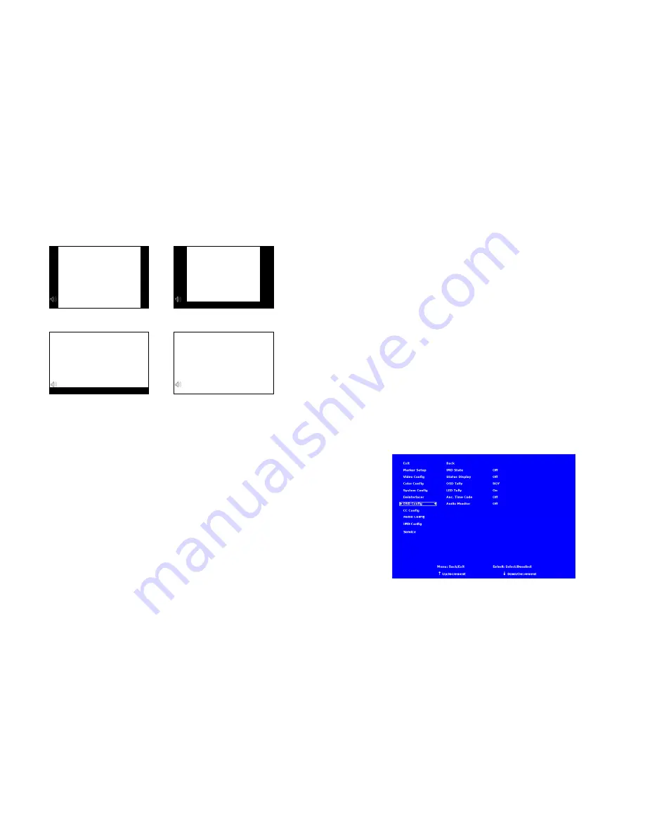
OSD CONFIGURATION SUBMENU

Use the OSD Configuration submenu to select a variety of information to be displayed on the screen.

OSD Configuration Submenu

Summary of Contents for V-R241-IMD-3G

Page 1: ...o honor the warranty If there is no proof of purchase provided with a warranty claim Marshall Electronics reserves the right not to honor the warranty set forth above Therefore labor and parts may be...

Page 2: ...2 This page intentionally left blank 31...

Page 3: ...he menu buttons 9 Using the RotoMenu knob 9 MARKER SETUP SUBMENU 10 VIDEO CONFIGURATION SUBMENU 12 COLOR CONFIGURATION SUBMENU 15 SYSTEM CONFIGURATION SUBMENU 16 DEINTERLACER SUBMENU 18 OSD CONFIGURAT...

Page 4: ...ut 4 Pin XLR Male Tally Hardware Interface HD 15 Female RS 422 485 Interface 2 x RJ12 Modular 6P6C TALLY GPI HARDWARE INTERFACE HD 15 Activation requires contact closure of pin to ground on the HD 15...

Page 5: ...lowing items are included V R241 IMD 3G Monitor V PS24 6 25 XLR R A DC Power Supply Operating Instructions Inspect the unit for any physical damage that may have occurred during shipping Should there...

Page 6: ...otocols IMD Fixed String Use this setting to display static IMD text on the screen This setting is used to enter IMD text locally when a serial protocol is not used for remote control The IMD Fixed St...

Page 7: ...void serial number conflicts with other Image Video devices on the same serial bus Each name can be up to 16 ASCII characters Press ENTER to edit the IMD Name Use the and buttons to move the cursor Pr...

Page 8: ...Ch Select Use this setting to select which of the 16 possible channels you would like to play on the Left side of the stereo output Right Ch Select Use this setting to select which of the 16 possible...

Page 9: ...menu buttons Press the MENU button to enter the main menu Use the and buttons to scroll through the main menu or each submenu Press the SELECT button to enter a submenu or choose a setting Press the...

Page 10: ...fe Area 88 Safe Area 80 Safe Area 1 85 1 Aspect Ratio 2 35 1 Aspect Ratio 4 3 Aspect Ratio 14 9 Aspect Ratio 13 9 Aspect Ratio 16 9 Marker Examples Marker Setup Submenu OFF No Marker 90 Safe Area 23 C...

Page 11: ...itor menu option to enable or disable the audio presence indicator icon When enabled this icon indicates whether embedded audio is present in the SDI video input A red circle and cross will flash on t...

Page 12: ...lue Only mode and adjust the Color knob so that the outermost bars white and blue appear to match in brightness Video Configuration Submenu 21 OSD Tally Use this setting to choose how tally is display...

Page 13: ...on to switch between several aspect ratio settings As the V R241 IMD 3G monitor has a native resolution of 1366x768 RGB pixels incoming images are automatically scaled to fit the screen In 4 3 mode im...

Page 14: ...s ignored 3 2 only Deinterlacer only recognizes content originating in 24fps and uses 3 2 film mode 25fps content is ignored Film Indicator Use the Film Indicator setting to enable or disable the film...

Page 15: ...ines or weaves each pair of fields into a progressive frame It is normal to see jagged artifacts on fast moving edges Film Mode Film mode uses specialized algorithms to correctly deinterlace content t...

Page 16: ...ing the knob twice Back Exit without making any changes Save Save current settings as defaults Mfg Return to the manufacturer s defaults all settings at 50 Saving and Loading User Presets Use the SAVE...

Reviews: