background image

Blastmaster

®

 Smart Box

6

Failure to comply with ANY NOTICE listed below could pose a hazard to personnel or property.

 

See Air & Abrasive Consumption Chart for estimated abrasive consumption rates and required air flow 

(cubic feet per minute). Your system must meet these minimum requirements to ensure proper function and 

performance.

 

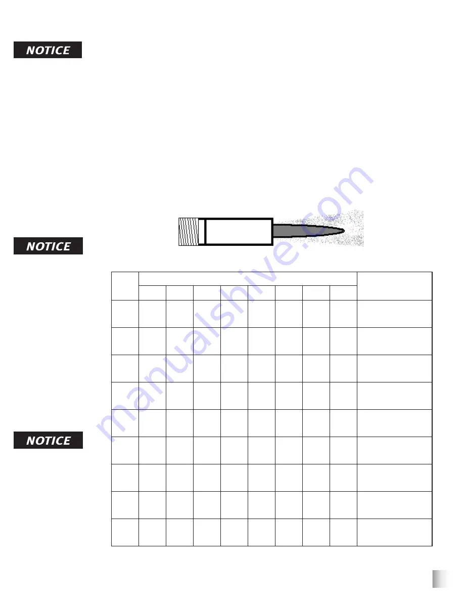
When it comes to air & abrasive mixtures, more is not necessarily better.  Optimum abrasive blasting efficiency 

takes place when a lean air & abrasive mixture is used. To correctly set the abrasive metering valve, begin 

with the valve fully closed and slowly increase the amount of abrasive entering the airstream. As you increase 

the abrasive flow, watch for a “blue flame” at the exit of the abrasive blasting nozzle. Faster cutting, reduced 

abrasive consumption and lower clean up costs, are benefits of the “blue flame”.

 

Abrasive blasting at optimal pressure for the abrasive used is critical to productivity. Example: For an abrasive 

with an optimal abrasive blasting pressure of 100 psi at the abrasive blasting nozzle, one pound per square inch 

of pressure loss will reduce abrasive blasting efficiency by 1.5%. A 10 psi reduction in air pressure will cause a 

15% loss of efficiency. Use a Needle Pressure Gauge to identify pressure drops in your system. Consult with 

your abrasive supplier for the requirements of your abrasive.

*Abrasive consumption is based on abrasive with a bulk density of 100 lbs per Cubic Foot

Air & Abrasive Consumption Chart*

Nozzle
Orifice

Pressure at the Nozzle (PSI)

Air (in cfm), Abrasive 

& Compressor 

Requirements

50

60

70

80

90

100

125

140

No. 2

(1/8ˮ)

11

67

2.5

13

77

3

15

88

3.5

17

101

4

18

112

4.5

20

123

5

25

152

5.5

28

170

6.2

Air (cfm)

Abrasive (lbs/hr)

Compressor Horsepower

No. 3

(3/16ˮ)

26

150

6

30

171

7

33

196

8

38

216

9

41

238

10

45

264

10

55

319

12

62

357

13

Air (cfm)

Abrasive (lbs/hr)

Compressor Horsepower

No. 4

(1/4ˮ)

47

268

11

54

312

12

61

354

14

68

408

16

74

448

17

81

494

18

98

608

22

110

681

25

Air (cfm)

Abrasive (lbs/hr)

Compressor Horsepower

No. 5

(5/16ˮ)

77

468

18

89

534

20

101

604

23

113

672

26

126

740

28

137

812

31

168

982

37

188

1100

41

Air (cfm)

Abrasive (lbs/hr)

Compressor Horsepower

No. 6

(3/8ˮ)

108

668

24

126

764

28

143

864

32

161

960

36

173

1052

39

196

1152

44

237

1393

52

265

1560

58

Air (cfm)

Abrasive (lbs/hr)

Compressor Horsepower

No. 7

(7/16ˮ)

147

896

33

170

1032

38

194

1176

44

217

1312

49

240

1448

54

254

1584

57

314

1931

69

352

2163

77

Air (cfm)

Abrasive (lbs/hr)

Compressor Horsepower

No. 8

(1/2ˮ)

195

1160

44

224

1336

50

252

1512

56

280

1680

63

309

1856

69

338

2024

75

409

2459

90

458

2754

101

Air (cfm)

Abrasive (lbs/hr)

Compressor Horsepower

No. 10 

(5/8ˮ)

308

1875

68.5

356

2140

79.5

404

2422

90

452

2690

100.5

504

2973

112

548

3250

122

663

3932

146

742

4405

165

Air (cfm)

Abrasive (lbs/hr)

Compressor Horsepower

No. 12 

(3/4ˮ)

432

2672

96

504

3056

112

572

3456

127

644

3840

143

692

4208

154

784

4608

174.5

948

5570

209

1062

6238

236

Air (cfm)

Abrasive (lbs/hr)

Compressor Horsepower

Inspect abrasive 

blasting nozzle before 

placing into service. 

Damage to abrasive 

blasting nozzle liner 

or jacket may occur 

during shipping. If you 

receive a damaged 

abrasive blasting nozzle, 

contact your distributor 

immediately for 

replacement. Abrasive 

blasting nozzles placed 

into service may not 

be returned. Abrasive 

blasting nozzle liners 

are made of fragile 

materials and can be 

damaged by rough 

handling and striking 

against hard surfaces. 

Never use a damaged 

abrasive blasting nozzle.

Replace abrasive 

blasting nozzle if liner 

or jacket is cracked 

or damaged. Replace 

abrasive blasting nozzle 

if original orifice size 

has worn 1/16” or more. 

Determine abrasive 

blasting nozzle wear by 

inserting a drill bit 1/16” 

larger than original size 

of abrasive blasting 

nozzle orifice. If the 

drill bit passes through 

abrasive blasting nozzle, 

replacement is needed.

“Blue Flame”

AIR & ABRASIVE CONSUMPTION CHART

Summary of Contents for BLASTMASTER SMART BOX

Page 1: ...employer of the user and or assistants must provide adequate and necessary training to ensure proper operation and compliance with all safety procedures pertaining to this equipment If Operator s Man...

Page 2: ...ipment As the largest provider of surface preparation and protective coatings equipment in the world our inventory levels and product availability are unmatched Logistics Services Marco s in house log...

Page 3: ...on which if not avoided could result in death or serious injury This is an example of a notice This indicates policy or practice directly related to safety of personnel or protection of property This...

Page 4: ...y Standards Inspect all equipment for wear or damage before and after each use Failure to use Original Equipment Manufacturer repair parts and failure to immediately replace worn or damaged components...

Page 5: ...n adequate concentrations To reduce conditions that could result in a fire or an explosion provide adequate ventilation eliminate all ignition or spark sources keep the work area free of debris store...

Page 6: ...me of air exists and petcock is unable to be left open at all times petcock should be opened frequently to release water To reduce abrasive intrusion in the air supply hose depressurize the abrasive b...

Page 7: ...r cfm Abrasive lbs hr Compressor Horsepower No 4 1 4 47 268 11 54 312 12 61 354 14 68 408 16 74 448 17 81 494 18 98 608 22 110 681 25 Air cfm Abrasive lbs hr Compressor Horsepower No 5 5 16 77 468 18...

Page 8: ...Blastmaster Smart Box 7 THE BIG PICTURE 3 5 7 4 4 3 2 1 8 9 17 14 16 15 13 19 18 10 20 23 21 4 24 27 26 25 22 28 5 3 6 11 12...

Page 9: ...ing Hose 19 and Air Hose 4 connection points Aftercooler and Moisture Separator Ensure Aftercooler 28 is positioned on stable ground Keep petcock drain of Moisture Separator 23 slightly open during us...

Page 10: ...Timers 5 Pressurize abrasive blasting pot See abrasive blasting pot Operator s Manual During use When abrasive blasting pot is pressurized greater than 3 PSI Red indicator light 8 will activate alerti...

Page 11: ...urces and lockout tagout all components before any maintenance or troubleshooting is attempted Failure to comply with the above warning could cause electrical shock and inadvertent activation of equip...

Page 12: ...are active An hour glass is displayed in the top left corner to indicate they are counting Note The timers count in increments of 6 minutes 0 1 6 minutes 0 5 30 minutes 1 0 1 hour OPERATING INSTRUCTI...

Page 13: ...g in death or serious injury W 562 Reset Production Timers Daily Production Timers 1 Open Cover 1 2 Select display to reset Push and hold correlating Reset Button 2 wait three seconds then release Thi...

Page 14: ...ulting in death or serious injury W 562 Install Blastmaster Smart Box on Bulk Abrasive Blasting Pot Note Additional components may be required to install Blastmaster Smart Box 1 Install Enclosure 10 t...

Page 15: ...ctivation of equipment resulting in death or serious injury W 562 Install Pressure Indicator Bulk Abrasive Blasting Pot Note Additional components may be required to install Pressure Switch 1 Disconne...

Page 16: ...equipment resulting in death or serious injury W 562 Install Pressure Indicator 6 5 cu ft and Smaller Abrasive Blasting Pots Note Additional components may be required to install Pressure Switch 1 Re...

Page 17: ...h the above warning could cause electrical shock and inadvertent activation of equipment resulting in death or serious injury W 562 Install Pressure Switch Blastmaster 125E 125P Remote Control System...

Page 18: ...trical shock and inadvertent activation of equipment resulting in death or serious injury W 562 Install Pressure Switch Blastmaster 123E 123P Remote Control System Note Additional components may be re...

Page 19: ...use electrical shock and inadvertent activation of equipment resulting in death or serious injury W 562 Install Pressure Switch Blastmaster 130P Remote Control System Note Additional components may be...

Page 20: ...ld cause electrical shock and inadvertent activation of equipment resulting in death or serious injury W 562 Install Pressure Switch Blastmaster 130E Remote Control System Note Additional components m...

Page 21: ...warning could cause electrical shock and inadvertent activation of equipment resulting in death or serious injury W 562 Install Pressure Switch Blastmaster 120E 120P Remote Control System Note Additi...

Page 22: ...omply with the above warning could cause electrical shock and inadvertent activation of equipment resulting in death or serious injury W 562 Note Mark control line and remote control system to aid con...

Page 23: ...ter 4 until reading matches analog gauge 6 Install Screws 2 and close Cover 1 MAINTENANCE Calibrate Digital Pressure Display Always depressurize the entire system disconnect all power sources and lock...

Page 24: ...et Daily Production Timers in Operating Instructions Check if other reset buttons are functioning properly Contact Marco for further assistance Blastmaster Smart Box indica tor lights are not illumina...

Page 25: ...Blastmaster Smart Box 24 MAINTENANCE NOTES DATE TYPE OF SERVICE PART NUMBER...

Page 26: ...Blastmaster Smart Box 25 DATE TYPE OF SERVICE PART NUMBER MAINTENANCE NOTES...

Page 27: ...THERS WITHOUT SELLER S PRIOR WRITTEN CONSENT IF SUCH NOTICE IS TIMELY GIVEN SELLER WILL HAVE THE OPTION TO EITHER MODIFY THE PRODUCT OR COMPONENT PART THEREOF TO CORRECT THE DEFECT REPLACE THE PRODUCT...

Page 28: ...BLAST IT 800 252 7848 ph 563 324 2519 fax 563 324 6258 40 NATIONWIDE SHIPPING LOCATIONS Marco Regional Branch Offices and Shipping Locations Direct Shipping Locations CONTACT MARCO 800 BLAST IT 800 25...

Reviews: