background image


24 

Ground Setting Phases 

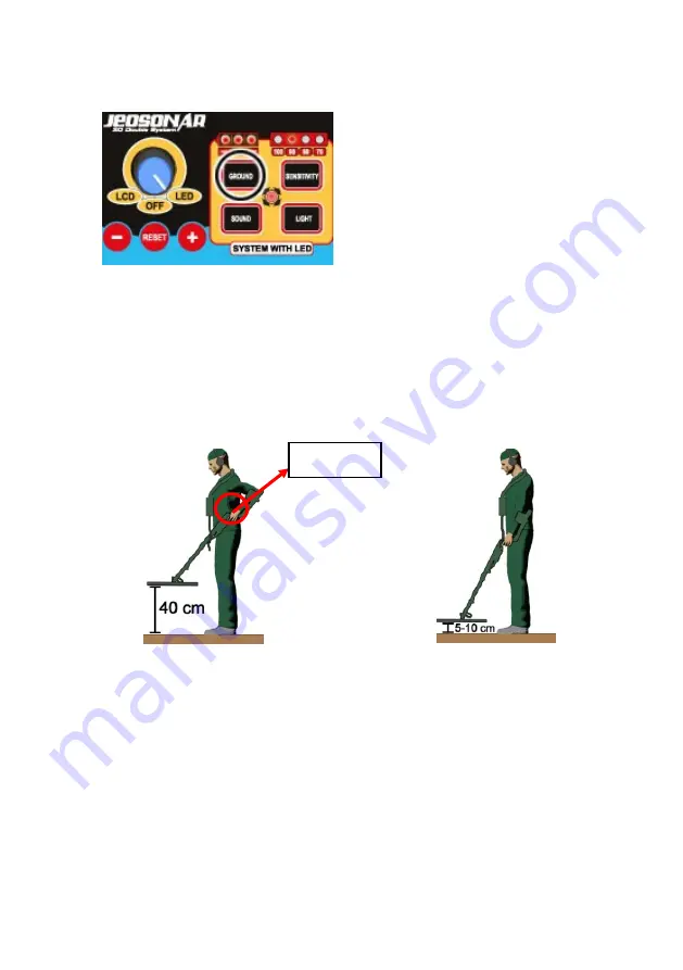
1. 

To make ground setting the device 

is  turned  on  in  “LED”  mode  and 
“GROUND” button is pressed.  


2. 

Make  sure  that  there  are  no  metals  or  voids  in  the  ground  where 

ground setting will be made. If ground setting could not be adjusted it will 
be repeated in a neighboring area. 

3. 

The operator lifts the detector head “

40

 cm” above ground and after 

resetting lower the detector head “

5-10

 cm” parallel to the ground. 


4. 

If  there  is  no  ground  effect  on  the  device,  none  of  “Cavity  and 

Mineral”  and  “Metal  and  Mineral”  lights  are  turned  on.  This  means  the 
device is suitable for exploring in that area. 

5. 

In  case  there  is  ground  effect  on  the  device,  the  “METAL  and 

MINERAL”  and  CAVITY  and  MINERAL”  lights  turn  on.  If  the  ground 
effect is powerful enough to turn two or more lights a sound alarm is also 
heard. In these circumstances ground setting should be made. 


Reset  


Summary of Contents for JEOHUNTER 3D Dual System

Page 1: ...1...

Page 2: ...arging the Battery 13 Using with LED System 17 What is Ground Setting and How it is done 22 Ground Setting Phases 23 Performing Search with LED System 29 Using with LCD System 33 How Ground Setting is...

Page 3: ...3 CAUTION PLEASE DO NOT START ASSEMBLING OR USING BEFORE READING THE WARNINGS SECTION...

Page 4: ...LE SHOCK 5 DO NOT EXPOSE THE DETECTOR HEAD TO DIRECT HEAT DO NOT EXERT FORCE DURING ASSEMBLY AND USE 6 THE BATTERY SHOULD BE DECENTLY PLACED IN ITS CASING AND CARE SHOULD BE TAKEN POLES ARE NOT CONNEC...

Page 5: ...5...

Page 6: ...6 PARTS AND ACCESSORIES...

Page 7: ...and displayed on the LCD monitor There is a carrying apparatus for easy transport of this system 2 210x315 Detector Head It is the system in 210x315 cm dimensions that consists of the detector head t...

Page 8: ...n only be used in LCD mode 4 600x1000 Detector Head and Carrying Case This is the detector head system developed for deep exploration that can be carried by two persons There is a separate carrying ca...

Page 9: ...0 240 V 50 60 Hz 1A City mains Output DC 12 16 8 V 400 mA Charge duration 10 hours 7 Carrying Case It is a case used for transport and storing of the System box the 210x315 Detector Head the 400x600 D...

Page 10: ...10 SYSTEM UNIT and JOYSTICK...

Page 11: ...et when pressed passing over it 2 ACCEPT The key that approves the related function and enable to switch to the previous menu 3 SETTING The key that allows switching to the Settings Menu 4 GROUND The...

Page 12: ...key used for adjusting illumination level in LED system 12 SENSITIVITY The mode that is used in LED system to make sensitivity settings 13 GROUND The transition key to switch to the necessary mode to...

Page 13: ...D indicates a considerable target 4 METAL and MINERAL When a metal or mineral is detected in exploration METAL and MINERAL LEDs glow Number of glowing lights varies depending on the power of detected...

Page 14: ...14 ASSEMBLY AND CHARGING THE BATTERIES...

Page 15: ...the sleeve The detector head is dismounted from the extension tube when packing in the carrying case Dismantling is carried out as the reverse of the process described above CAUTION Do not take apart...

Page 16: ...ure is connected to socket A on the system box EARPHONE CONNECTION Enables signal sound to be switched from external loudspeaker to the earphone The C plug shown in the figure in the previous page is...

Page 17: ...ow blinks repeatedly and infrequent beeps are heard This indicates that the battery is full Detection and Charging of a Depleted Battery When a depleted battery is connected to the charger green light...

Page 18: ...18 USING WITH LED SYSTEM...

Page 19: ...tus by the aid of LEDs that indicate battery charge level Checking Battery Charge Status Look at the battery charge indicator on the device If three lights are on it means that the battery is fully ch...

Page 20: ...pressed again to switch to Explore mode ATTENTION In the LED system if LED SOUND SENSITIVITY GROUND sections are selected the light in the middle is lit to inform the operator that the device is not i...

Page 21: ...erator by producing different tone sounds depending on Void and Metal directions Using the Reset Button When the device is in use some interference may occur due to the environment or unbalanced detec...

Page 22: ...easily Since this step enhances the sensitivity and power of the device it will be more affected from the ground and operation will get harder For this reason the ground setting should be done as corr...

Page 23: ...mportant provisions of exploration Therefore the operator should be a keen observer and should be able to detect variations in the ground He has to observe soil compositions continuously to be able to...

Page 24: ...40 cm above ground and after resetting lower the detector head 5 10 cm parallel to the ground 4 If there is no ground effect on the device none of Cavity and Mineral and Metal and Mineral lights are t...

Page 25: ...detector head again 5 10 cm distance to the ground If the ground effect on the device is eliminated by this procedure none of Metal and Mineral lights turn on Cavity and Mineral lights should also no...

Page 26: ...tance If the lights are on and sound alarm continues after each operation the number of lights will decrease continue this operation until the effect is eliminated 7 If CAVITY and MINERAL warning is r...

Page 27: ...ontinues the device will keep turning on Void and Mineral lights and sound alarm In this case lift the detector head of the device 40 cm above ground again and press button a couple of times perform r...

Page 28: ...carry out exploration when a single light is on Metal and Mineral and Void and Mineral side NOTE Lower gets the sensitivity levels lower is the sensitivity in detecting metals NOTE Exploration should...

Page 29: ...29...

Page 30: ...30 EXPLORE MODE WITH LIGHT SYSTEM...

Page 31: ...to the power of the signal When the device detects a void it gives a sound alarm and VOID and MINERAL lights turn on the screen according to the power of the signal If our target is metal or void the...

Page 32: ...nd warns the operator The operator receiving this warning press the SCAN button on the joystick and makes a second pass over the target After this operation if PRECIOUS light keeps on it can be said t...

Page 33: ...33...

Page 34: ...34 USING WITH LCD MODE...

Page 35: ...ystem the other is LCD System To switch the device to LCD System the commutator switch is adjusted to LCD After the device is switched on the operator makes the desired language selection by using and...

Page 36: ...s authorized service should be called Checking Battery Charge Level The device switches to Ground Adjustment section after it detects the detector head At the bottom of this section there is an area t...

Page 37: ...ACCEPT button the light indicator bar will turn from yellow into green Adjust the light level by pressing and keys and press ACCEPT button The green indicator bar turns back into yellow Now the light...

Page 38: ...t of SENSITIVITY Level SETUP button is pressed for adjusting the level of sound of the device in whatever mode is it in The current adjusted sensitivity level is displayed as on the screen Select the...

Page 39: ...rence may occur due to the environment or unbalanced detector head movement These interferences start to show on the screen and cause the device to give a sound alarm Resetting can be done by pressing...

Page 40: ...ings after checking existing settings Ground Setting Phases 1 When the device is switched on in LCD mode ground adjustment is displayed automatically 2 Lift the detector head 40 cm above ground and pr...

Page 41: ...100 Completed expression is displayed In this case the device is ready for exploring and you may switch to explore mode by pressing the ACCEPT button 7 In case there is ground effect on the device an...

Page 42: ...detector head 5 10 cm above ground if ground effect persists try to eliminate this effect by pressing or buttons 9 If we are not able to eliminate the ground effect decrease the sensitivity level one...

Page 43: ...43...

Page 44: ...44 EXPLORE MODE WITH LCD SYSTEM...

Page 45: ...teraction occur on CAVITY METAL IRON and VALUABLE bars according to the power of the signal At the same time the effect of the target can be monitored on the graph above the bars Metal targets are ind...

Page 46: ...e magnitude of the effect When an alarm is received from the device over any point the device is taken away from the target and reset in an area where no signal is received and the detector head is pa...

Page 47: ...vice will filter worthless metals To be able to detect worthless metals again this mode should be switched back to ON mode by repeating above mentioned operation Getting and Analysis report by Analyzi...

Page 48: ...he ACCEPT button after forming this frame In this menu it is explained to the in detail how to determine the dimensions of the target To enter the determined width dimension place the yellow frame on...

Page 49: ...ss the ACCEPT button to leave this report Switched back to Depth mode and switched to explore mode by pressing the DEPTH button Recording and Examination of Records The device can record the analysis...

Page 50: ...Erase record and Exit windows Use the and keys to activate these windows Press ACCEPT button when there is a frame around Exit window to exit from the record menu Press the ACCEPT button and approve...

Page 51: ...51 TECHNICAL PROPERTIES...

Page 52: ...52...

Page 53: ...53...

Reviews: