16
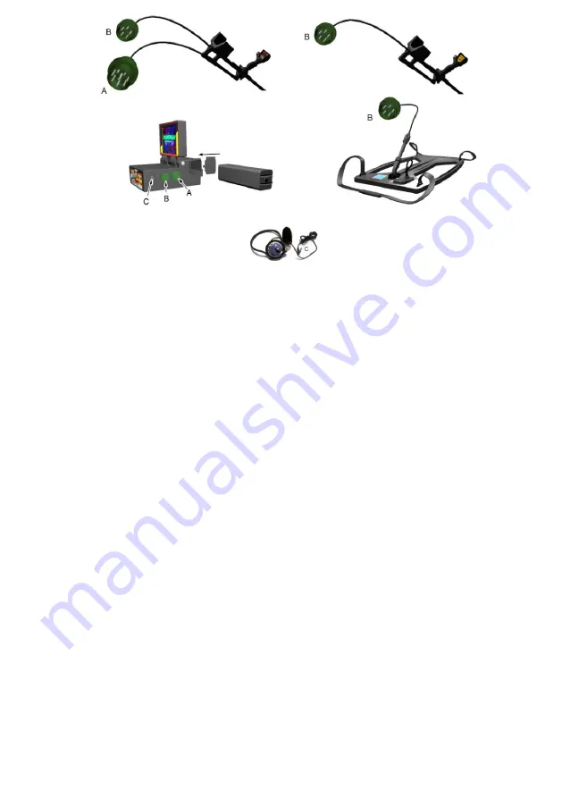
DETECTOR HEAD CONNECTION
Transmits the data received from detector head to the Electronic system
box. The 5 pin “B” plugs shown in the above figure are connected to
socket “B” on the system box.
JOYSTICK CONNECTION
Joystick transmits the received data to the Electronic system box. The 8
pin “A” plug shown in the above figure is connected to socket “A” on the
system box.
EARPHONE CONNECTION
Enables signal sound to be switched from external loudspeaker to the
earphone. The “C” plug shown in the figure in the previous page is
connected to socket “C” on the system box.
BATTERY CONNECTION
The batteries shown in the previous page is located in the direction of the
arrow in the system box and battery compartment lid is closed. The
battery is so placed that the poles on the battery is in contact with the
springs mounted in the battery compartment.
Summary of Contents for JEOHUNTER 3D Dual System
Page 1: ...1...
Page 3: ...3 CAUTION PLEASE DO NOT START ASSEMBLING OR USING BEFORE READING THE WARNINGS SECTION...
Page 5: ...5...
Page 6: ...6 PARTS AND ACCESSORIES...
Page 10: ...10 SYSTEM UNIT and JOYSTICK...
Page 14: ...14 ASSEMBLY AND CHARGING THE BATTERIES...
Page 18: ...18 USING WITH LED SYSTEM...
Page 29: ...29...
Page 30: ...30 EXPLORE MODE WITH LIGHT SYSTEM...
Page 33: ...33...
Page 34: ...34 USING WITH LCD MODE...
Page 43: ...43...
Page 44: ...44 EXPLORE MODE WITH LCD SYSTEM...
Page 51: ...51 TECHNICAL PROPERTIES...
Page 52: ...52...
Page 53: ...53...


