


13 ENGLISH
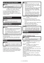
(For all models)
14
12
11
15
13
17
16
18
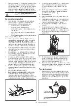
Cord hook
1
2
3
4
5
6
7
9
8
10
11
12
13
Spike bumper
18
14
15
16
17
Rear handle
Switch trigger
Oil filler cap
Front handle
Front hand guard
Guide bar
Saw chain
Lever
Adjusting screw/dial
Oil level sight
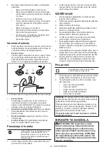
Rear hand guard
Lock-off button
Chain catcher
Guide bar cover
Adjusting screw for oil pump
(at the bottom)
Sprocket cover
ASSEMBLY
CAUTION:
•
Always be sure that the tool is switched off and
unplugged before carrying out any work on the
tool.
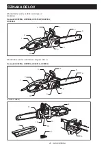
Removing or installing sprocket
cover
To remove the sprocket cover, perform the following
steps:
(For nut models)
►
Fig.1
Loosen the nut.
(For lever models)
►
Fig.2:
1.
Lever
2.
Sprocket cover
Press and fully open the lever until it stops.
Turn the lever counterclockwise.
To install the sprocket cover, perform the above steps
in reverse.
Removing or installing saw chain
CAUTION:
•
Always wear gloves when installing or removing
the saw chain.
To remove the saw chain, perform the following steps:
1.
Loosen the sprocket cover.
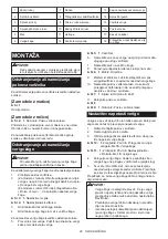
2. (For nut models) Turn the chain adjusting screw
counterclockwise to release the saw chain ten-
sion.
(For lever models) Turn the adjusting dial to "-"
direction to loosen the saw chain tension.
►
Fig.3:
1.
Adjusting screw
►
Fig.4:
1.
Adjusting dial
3.
Remove the sprocket cover.
4.
Remove the saw chain and guide bar from the
chain saw.
To install the saw chain, perform the following steps:
5.
Make sure the direction of the chain. The arrow
mark on the chain shows the direction of the
chain.
►
Fig.5:
1.
Sprocket
6.
Fit in one end of the saw chain on the top of
the guide bar and the other end of it around the
sprocket.
7.
Place the guide bar on the chain saw.


