


P 1
1
/ 1
1
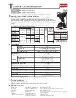
Fig.D-8 (Specifications for LXDT03/ LXDT04)
Fig.D-9
W
iring diagram
20
°
Tilt Insulated terminals on
Lead wires’ ends to
20
°
from the vertical line
on the machine.
Brush holder
complete
Switch
Seal
Connectors
LED job light
Do not put any Lead wires
on Seal.
Lead wire holders
Lead wires connected to each connector
have to be fixed into Lead wire holders.
Receive the tube for Lead wires
with the groove of Sponge A.
Sponge A
Lead wires have to be passed over the center of Terminal
with the flag terminal ends set in place.
Flag terminals
The center of Terminal


