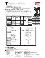
background image

  8

/ 1

1

C

ircuit diagram

C

ircuit diagram

White

Yellow

Color index of lead wires' sheath

Black
Red

Switch

Terminal

+

Line filter

Heat shrink tube

Line filter

Line filter is not used

for some countries

Fig. D-1 (Specifications)

Fig. D-2 ( Specifications for LXDT03/ LXDT04)

Connector

(3P)

LED

Light circuit

Brush holder

complete

M2

M1

Blue

White lead wire is used


for

some countries.

Heat shrink tube

Heat shrink tube

Heat shrink tube

White

Yellow

Color index of lead wires' sheath

Black
Red

Switch

Terminal

Connector

LED

Brush holder

complete

M2

M1

AS

+

AS

Summary of Contents for LXDT04

Page 1: ...3 200 160 1 630 1 420 Standard bolt High tensile bolt Machine screw Driving shank M5 M14 3 16 9 16 M5 M12 3 16 1 2 Coarse thread screw 22 125mm 7 8 4 7 8 M4 M8 5 32 5 16 Yes Yes Yes Reverse switch Yes 1 3 3 1 5 4 2 8 3 3 3 4 1 3 3 0 battery BL1815 BL1830 Li ion 220 approx 15 22 with DC18RC or DC18RA 6 35mm 1 4 Hex This product is available in the following variations Phillips bits Socket bits Dril...

Page 2: ...oving Ring spring 11 from Bit holder section 1R223 1R224 1R232 1R288 1R291 134847 1 134848 9 Use for removing Steel balls Fig 1 16 21 25 27 28 Spur gear 22 Apply the following lubricants to protect parts and product from unusual abrasion Fig 1 Item No Description Anvil Steel ball 3 5 24pcs Steel ball 5 6 2pcs Hammer case complete Inside of Sleeve 14 which touches 19 Hole into which 27 Spindle top ...

Page 3: ... Tapping screws on Housing set R and then remove Housing set R Fig 5 5 Remove an assembled part consists of three sections from Housing set L Fig 6 6 Pull out Hammer section from the other sections Fig 7 Rear cover Bumper hook of Hammer case cover hook of Hammer case cover Hammer case complete Slotted screwdriver Slotted screwdriver 3x16 Tapping screw 2pcs 3x16 Tapping screw 8pcs Housing set R Hou...

Page 4: ...et 1R224 and 134847 1 to 1R223 and then fit the hexagonal portion on Hammer case complete into 134847 1 and turn 1R223 counterclockwise Note The fastening torque has to be 30N m to 40N m 3 Hook Hammer case cover to the hexagonal portion of Hammer case complete and then fit its hooks to the depressions on the reverse of Bumper P 4 11 Repair Hexagonal portion of Bearing box complete Hexagonal portio...

Page 5: ...assembling the motor section to Bearing box complete insert Armature drive end into Internal gear 51 engaging with Spur gears 22 Figs 13 and 1 When the assembled sections Hammer section motor section and Brush holder section is set on Housing set L fit the projection of the housing into the notch on Yoke unit Figs 13 and 6 Be sure to check the following positions as drawn in Fig 14 1 Flat portion ...

Page 6: ... Notch of F R change lever Projection of Switch P 6 11 Repair Sponge A Seal Sponge B Rib of Housing set R Housing set L 3 4 Disassembling Bit holder section 1 Remove Hammer section by steps drawn in Fig 2 to Fig 7 2 Remove the following parts from Hammer section Figs 8 9 and 10 Hammering mechanism Internal gear 51 O ring 40 and Bearing box complete 3 Put Hammer case complete on 1R232 to disassembl...

Page 7: ...rned upside down from shown in Fig 23 to Fig 24 to prevent Steel balls 3 5 from being dropped There are 24pcs of Steel balls 3 5 in the groove of Hammer As drawn in Fig 25 the groove is designed to have a space equivalent to one Steel ball 3 5 P 7 11 Repair Fig 23 Fig 24 Fig 25 Right Wrong Hammer Hammer Hammer Spindle end Spindle end Spindle end Spindle top 1R045 Top of Cam groove on Spindle Openi...

Page 8: ...not used for some countries Fig D 1 Specifications Fig D 2 Specifications for LXDT03 LXDT04 Connector 3P LED Light circuit Brush holder complete M2 M1 Blue White lead wire is used for some countries Heat shrink tube Heat shrink tube Heat shrink tube White Yellow Color index of lead wires sheath Black Red Switch Terminal Connector LED Brush holder complete M2 M1 AS AS ...

Page 9: ... between Rib and Boss is allowed to use as Lead wire holder LED 20º Assemble Lead wire red with M1 terminal to Switch vertically Assemble Lead wire black with M2 terminal to Switch at approx 20 left from the vertical line Assemble each Lead wire connecting terminal to Switch at approx 20 left from the vertical line Fully bend M2 terminal of Lead wire black to reserve the space for Line filter M1 T...

Page 10: ...e A Lead wire holders 20 Brush holder complete Switch LED job light Do not put any Lead wires on Seal Lead wires connected to each connector have to be fixed into Lead wire holders Sponge A Connectors Tilt Insulated terminals on Lead wires ends to 20 from the vertical line on the machine Seal Do not put any Lead wires on Seal Lead wire holders Lead wires connected to each connector have to be fixe...

Page 11: ...mplete Switch Seal Connectors LED job light Do not put any Lead wires on Seal Lead wire holders Lead wires connected to each connector have to be fixed into Lead wire holders Receive the tube for Lead wires with the groove of Sponge A Sponge A Lead wires have to be passed over the center of Terminal with the flag terminal ends set in place Flag terminals The center of Terminal ...

Reviews: