[2] LUBRICATION
[3] DISASSEMBLY/ASSEMBLY
[3] -1. Chuck Section
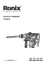
Apply the following Makita grease to protect parts and product from unusual abrasion.
* Grease RB No.00 to the portions marked with black triangle
* Molybdenum disulfide lubricant to the portions marked with gray triangle
Fig. 2
Fig. 3
Fig. 4
Fig. 5
Fig. 6
Fig. 7
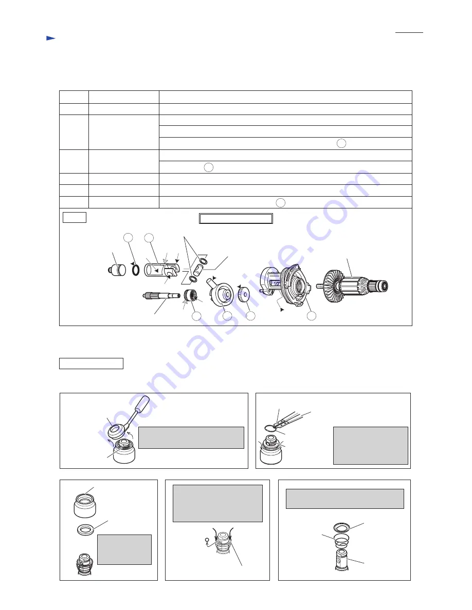
DISASSEMBLING
Item No.
Striker
Disassemble Chuck section in the order
from Fig. 3 to Fig. 7
.
Spur gear 10
Cap 35
Remove Ring spring 19
from the groove on Tool
holder complete using
1R003 and 1R212.
Pushing Guide washer in the
direction of arrow, remove
Steel ball 7.0 from the slot on
Tool holder complete.
Guide washer and Conical compression
spring 21-29 can be removed.
Chuck cover and
Ring 21 can be
removed.
Remove Cap 35 by hand and using
a slotted screwdriver.
Ring spring 19
Tool holder
complete
Ring spring 19
Piston joint
Armature
Flat washer 12
Swash Bearing Section
Description
Portion to lubricate
44
46
47
56
44
46
47
56
35
35
36
36
Clutch cam
Swash bearing 10
Helical gear 26
Inner housing cmplete
O ring 16
Piston cylinder
Whole portion
Pole portion which is inserted into Piston joint
Teeth portion
Space where Armature's drive end and 47 Helical gear 26 engages
(f) Inside where Striker moves
(g) Hole for accepting Piston joint
(h) Apply Molybdenum disulfide lubricant to Surface where 25 Tool holder contacts.
(f)
(g)
(h) (g)
(i)
(i) Apply Molybdenum disulfide lubricant to the groove.
(j)
(j) Side where 46 Swash bearing 10 engages
Chuck cover
Guide washer
Tool holder
complete
Conical
compression
spring 21-29
Ring 21
Steel ball 7.0
Guide washer
1R003
1R212
R
epair for 2 mode Rotary hammers HR2230, HR2460 and HR2460F
P
3
/
15