BLUEPIRAT2 | USER MANUAL/
page 81 of 82
18
List of tables
Table 4.1: Additional features by optional licenses ................................................................... 11
Table 5.1: Model versions of BLUEPIRAT2 / BLUEPIRAT2 5E ................................................ 14
Table 6.1: LED behavior ........................................................................................................... 17
Table 6.2: Interface abbreviations and status information ......................................................... 19
Table 8.1: Accuracy of marker .................................................................................................. 32
Table 8.2: Standby mode
– [W= wake up A= keep alive] .......................................................... 33
Table 8.3: Status Logger: OK ................................................................................................... 34
Table 8.4: Status Logger: RING ............................................................................................... 34
Table 8.5: Status Logger: MEM ................................................................................................ 35
Table 8.6: Status Logger: Memory Full ..................................................................................... 35
Table 8.7: Status Logger: ERROR ........................................................................................... 35
Table 9.1: CAN ......................................................................................................................... 36
Table 9.2: LIN ........................................................................................................................... 38
Table 9.3: Serial interface ......................................................................................................... 39
Table 9.4: FlexRay ................................................................................................................... 39
Table 9.5: MOST25 data logging .............................................................................................. 42
Table 9.6: MOST150 data logging ............................................................................................ 42
Table 10.1: Conversion options (overview) ............................................................................... 44
Table 12.1: Datasheet .............................................................................................................. 49
Table 14.1: Extension harness (overview) ................................................................................ 54
Table 14.2: MQS 54pin............................................................................................................. 56
Table 14.3: Pin assignment of the BLUEPIRAT2 multi-function connector ............................... 57
Table 14.4: Pin assignment of the BLUEPIRAT2 5E multi-function connector .......................... 58
Table 14.5: BLUEPIRAT2 5E
– power harness ........................................................................ 59
Table 14.6: Pin assignment of the BLUEPIRAT2 5E
– power harness ..................................... 59
Table 14.7: D-Sub 26pin ........................................................................................................... 61
Table 14.8: Pin assignment of the Digital/Analog connector ..................................................... 61
Table 14.9: Mini D Ribbon 3M 26pin......................................................................................... 62
Table 14.10: Pin assignment of the Analog/Digital connector ................................................... 63
Table 14.11: FCI-Connector (Cable assembly 50 cm) .............................................................. 63
Table 14.12: Pin assignment of the Ethernet connector............................................................ 64
Table 14.13: Mini D Ribbon 3M 14pin ....................................................................................... 65
Table 14.14: Pin assignment of the FlexRay connector ............................................................ 65
Table 14.15: D-SUB 44pin ........................................................................................................ 66
Table 14.16: Pin assignment of the CAN/FlexRay connector ................................................... 67
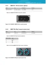
Table 14.17: MOST25 / MOST150 Connector (optical) ............................................................ 68
Table 14.18: MOST150 cPhy Connector (electrical) ................................................................. 68
Table 14.19: Pinning MOST150 cPhy Connector (electrical) .................................................... 68
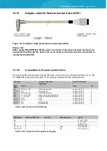
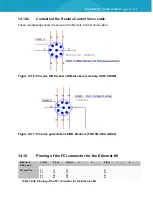
Table 14.20: Contacts of the DIN plug ...................................................................................... 69
Table 14.21: Contacts of the angeled Lemo plug...................................................................... 69
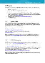
Table 14.22: Pinning of the FCI connector for the Ethernet-Kit ................................................. 70
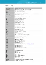
Table 16.1: Abbreviations ......................................................................................................... 79


