BLUEPIRAT2 | USER MANUAL/
page 29 of 82
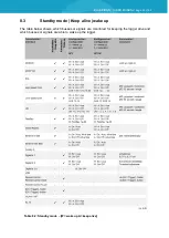
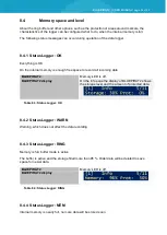
7.4
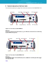
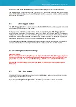
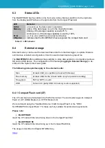
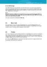
Interfaces at the rear side
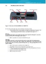
Figure 7.9: Rear side of the BLUEPIRAT2 with MOST150
On the various data logger types are the following connectors possible:
multi function connector: This connector contains the remaining lines for power, High
Speed CAN 1-12, Low Speed CAN 12-13, Remote Control Voice, LIN 1-8.
The pin assignment of this connector is described in the chapter 14.1.
Warning:
It is possible that devices connected to the data logger might be damaged in case of an
incorrect polarity of the data logger power supply.
MOST: A standard 2+0 connector for MOST fiber optic.
Important:
If the MOST connector is not used, the jack must be covered with a terminating plug.
This prevents the sensitive fiber optic contacts from getting dirty. It also makes sure that
the data logger does not start up unintentionally when, e.g., strong sunlight falls onto the
optical contacts.
serial: This connector is described in the chapter 9.3.
analog/digital: This connector is described in the chapter 14.6.
FlexRay: One connector for two interfaces with a/b. The pin assignment of this con-
nector is described in the chapter 14.10.
Ethernet: connector for optional Ethernet-Kit
USB: not used in the moment

