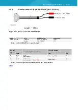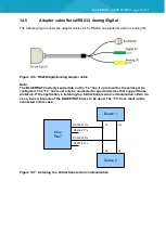
BLUEPIRAT2 | USER MANUAL/
page 63 of 82
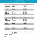
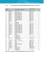
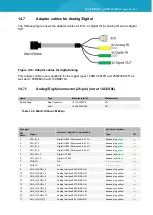
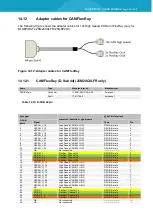
Table 14.10: Pin assignment of the Analog/Digital connector
14.8
Ethernet kit for BLUEPIRAT2
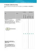
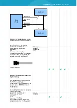
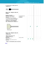
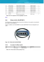
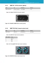
The following figure shows the Ethernet box with four interfaces. This would be connected with
a FCI-cable to the BLUEPIRAT2.
This kit is available only for BLUEPIRAT2 because BLUEPIRAT2 5E has an integrated 4-port
switch.
Figure 14.9: Ethernet kit for BLUEPIRAT2
14.8.1
Connector for Ethernet-Kit
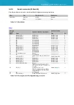
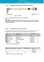
Table 14.11: FCI-Connector (Cable assembly 50 cm)
18
ANA_IN_GND_4
Analog Interface #04 GROUND
banana plug yellow
----
19
ANA_IN_GND_5
Analog Interface #05 GROUND
banana plug yellow
----
20
ANA_IN_GND_6
Analog Interface #06 GROUND
banana plug yellow
----
21
ANA_IN_GND_7
Analog Interface #07 GROUND
banana plug yellow
----
22
ANA_IN_GND_8
Analog Interface #08 GROUND
banana plug yellow
----
23
ANA_IN_GND_9
Analog Interface #09 GROUND
banana plug yellow
----
24
ANA_IN_GND_10
Analog Interface #10 GROUND
banana plug yellow
----
25
SHIELD
NA
-----------------------
----
26
ECL_IN
Electrical Control Line (SMSC)
DSUB-9 / male
7
Name
Type
Manufacturer-Nr.
Manufacturer
FCI
Cable Assembly
10054999-R0050Aulf
FCI

