Product description
11
© Lutz-Jesco GmbH 2020
Subject to technical changes.
200318
BA-10491-02-V01
Piston diaphragm dosing pump
MEMDOS KMS LB/LA
Operating instructions
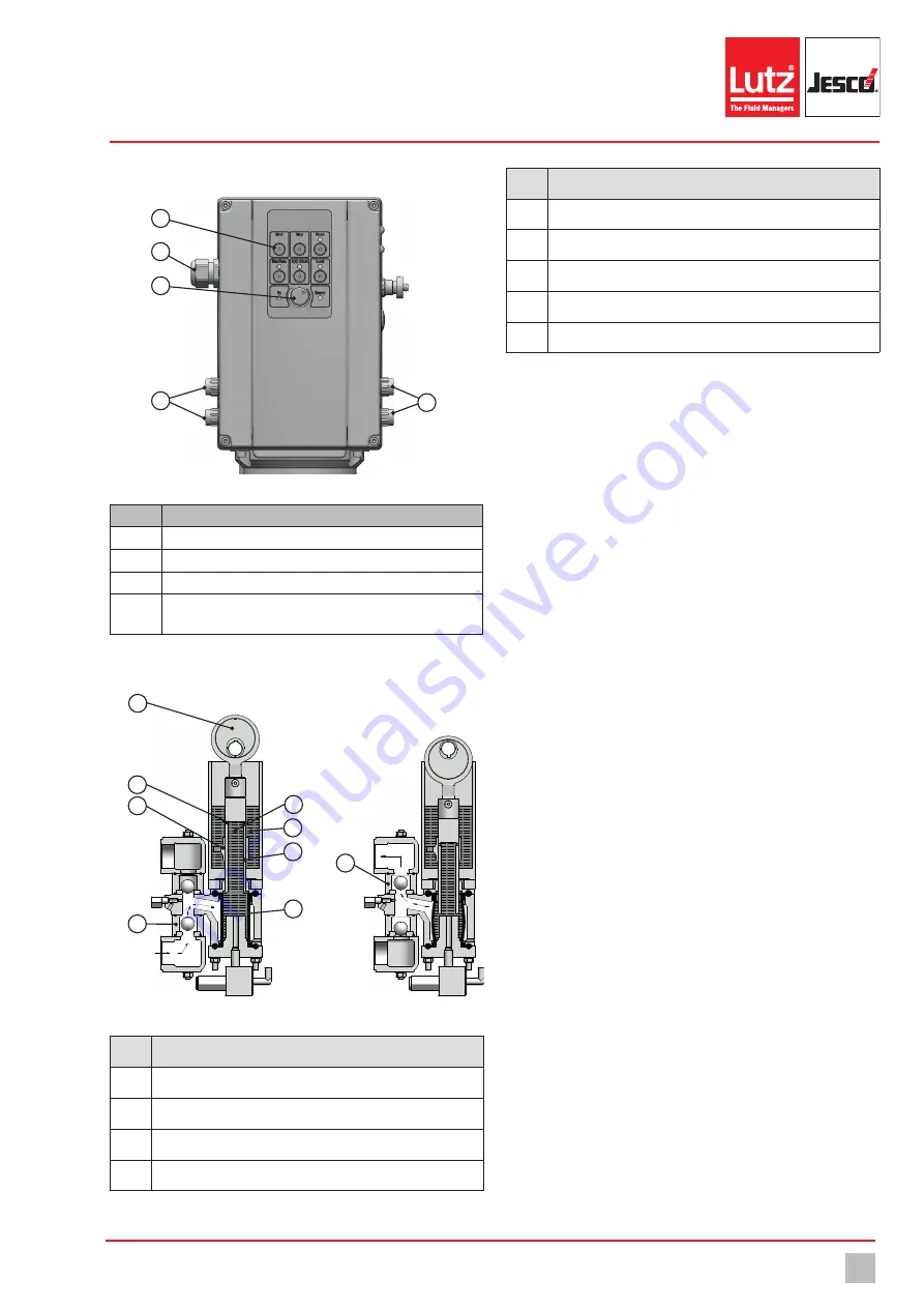
4.4 Control elements MEMDOS KMS LA
1
3
2
4
4
Fig. 2: Control elements
Item
Description
1
multifunction buttons
2
Power supply connection
3
Potentiometer
4
Connection sockets for external operation or connecting
accessories
Tab. 6: Designation of the control elements
4.5 Function description MEMDOS KMS LB/LA
10490000
Bild BA MEMDOS KMS LB 14
4.4 Funktionsbeschreibung
1
8
9
6
3
4
5
7
2
Fig. 3: Cross section MEMDOS KMS LB/LA dosing head (left: suction stroke, right: pressure
stroke)
No.
Description
1
Connecting rod
2
Hose diaphragm
3
Pressure valve
4
Discharge opening
Tab. 7: Pos. numbers dosing head MEMDOS KMS LB/LA
No.
Description
5
Slide valve
6
Suction valve
7
Piston
8
Reservoir
9
Oil
Tab. 7: Pos. numbers dosing head MEMDOS KMS LB/LA
Dosing units for the dosing of liquids are usually dosing pumps with an
oscillating or rotating displacement body. The MEMDOS KMS LB/LA
works with an oscillating piston driven via a worm gear by an electrical
motor. The worm gear and the hydraulic system of the pump are operated
using the same oil (9).
An eccentric in the pump housing is put into rotation by a worm gear. The
eccentric is connected with the piston (7) via a connecting rod (1) and
converts the rotation movement of the motor into an oscillating move-
ment of the piston. If the piston moves downwards, the hydraulic fluid in
the pump is pressurized. This stretches the hose diaphragm (2) and the
medium in the dosing head is pressed out via the pressure valve (3). The
piston is equipped with an axial flow opening at its lower end; this con-
cludes in a radial discharge opening (4) at its upper end. A downwards
piston movement following a set partial stroke (stroke adjustment unit)
works to displace the hydraulic fluid through the flow opening into the
reservoir (8) next to the piston. The actual delivery rate is set via a slide
valve (5) which is positioned vertically using a control rod. As long as the
radial opening in the piston is not covered by the slide valve, the dis-
placed hydraulic fluid moves upwards, back through the flow opening
into the hydraulic fluid chamber and no process fluid is transported. If the
piston moves downwards whilst the radial opening is covered by the slide
valve, hydraulic fluid cannot escape through this opening and the hose di-
aphragm will be stretched to its maximum extent. If the piston reaches its
lower end position and starts to return upwards, the hose diaphragm will
relax to its original position. The resulting negative pressure in the dosing
head effects suction of the process fluid through the suction valve (6). The
hose diaphragm returns from its extension to a fixed position with every
stroke. This position represents a perforated support pipe, which secures
unchanging accuracy by maintaining the end position of the diaphragm. If
the piston reaches the upper end position, a pump cycle has been com-
pleted and the next cycle can begin. The hydraulic reservoir and the dos-
ing head are designed to remove any developing gas bubbles (foam) with
every stroke. This is achieved in the pump housing by the ability of the
gas bubbles to rise through the piston into the chamber. In the dosing
head itself, the opening of the flow channel rises continually to the pres-
sure valve without impediments for the gas bubbles. To fill and vent the
hydraulic system with every stroke, the upper position of the slide valve is
applied in such a way that the radial opening in the piston is opened for a
certain part of the piston movement.


