Operation
30
© Lutz-Jesco GmbH 2020
BA-10491-02-V01
Piston diaphragm dosing pump
MEMDOS KMS LB/LA
Operating instructions
11 Operation
WARNING
Caustic burns or other burns through dosing media!
After connecting the mains supply, residual dosing media in the dosing
head can spray out.
ð
Wear the recommended personal protective equipment.
ð
Make sure that the materials you are using are suitable for the dos-
ing medium.
ð
Make sure that the lubricants, adhesives, sealants, etc. that you use
are suitable for the dosing medium.
ð
Install a leakage drain.
ð
Install pressure relief valves.
CAUTION!
Danger of automatic start up!
The dosing pump does not have an ON/OFF switch and may start to
pump as soon as it is connected to the mains supply. This means that
dosing medium can escape. Depending on the type and hazardousness
of the dosing medium, this can result in injury.
ð
Set the stroke length setting to 0 % before disconnecting it from the
power supply.
ð
Ensure that the dosing pump has been installed correctly before
connecting it to the mains supply.
PLEASE NOTE
Overheating of the motor
If the fan cover is removed or is defective, insufficient motor cooling
is provided.
ð
Before starting the dosing pump, ensure that the motor fan cover
is fitted and fully functional.
11.1 Commissioning the dosing pump
i
For initial commissioning, it is advisable to use water as the
dosing medium to check that the system is leak-proof and that
the dosing pump is functioning correctly. Check first whether
undesirable reactions could occur between the actual dosing
medium and the water.
At initial commissioning, it is advisable to prime the pump
without backpressure. For this purpose, we recommend
installing a relief valve on the discharge side of the dosing
pump.
Precondition for action:
ü
The dosing pump has been assembled and installed in accordance
with chapter 7 Installing the Dosing Pump“ on page 18, chapter 8
Hydraulic installations“ on page 19 and chapter 9 Electrical instal-
lation“ on page 22.
ü
All the mechanical fastenings have been inspected to ensure ade-
quate load-bearing capacity.
ü
The dosing head screws have been tightened with the correct torque
(see chapter 12.3 Tightening the dosing head nuts“ on page 34).
ü
All the hydraulic sections have been inspected to ensure they are ad-
equately leak-proof and that the through flow direction is correct.
ü
The drive motor and all associated additional equipment is checked
for proper connection.
ü
Personnel have read all the operating instructions and understood
them completely.
Resources required:
@
Gear oil of the viscosity class ISO-VG100 (SAE 40). The filling capacity
is about 3 l.
1
2
4
3
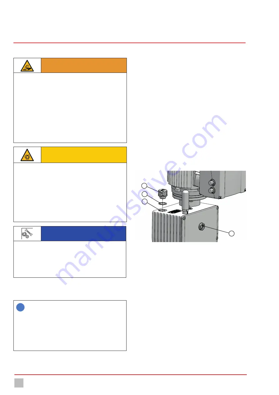
Fig. 14: Dosing pump oil inlet
Perform the following working steps:
1.
Unscrew the closing screw (1) from the oil inlet (3) and remove the
seal (2).
2.
Fill oil in the oil inlet. Check the oil level in the oil level glass (4) at the
same time. The oil level should reach to c. the middle of the oil level
glass.
3.
Place the washer seal (2) onto the oil inlet (3) and tighten up the clos-
ing screw.
4.
If present, open the pressure and suction side shut-off valves.
5.
Connect the dosing pump to the power supply.
ü
The dosing pump is commissioned.


