Control
25
© Lutz-Jesco GmbH 2020
Subject to technical changes.
200318
BA-10491-02-V01
Piston diaphragm dosing pump
MEMDOS KMS LB/LA
Operating instructions
10 Control
10.1 Stroke length adjustment
The desired delivery rate of the dosing pump is set using the stroke
length adjustment. Turning the adjustment knob increases or decreases
the hub length and so the amount of dosing media from the dosing head.
The stroke length can be adjusted while the pump is running or while it is
turned off (in depressurized condition).
10490000_3
Bild BA MEMDOS KMS LB 14
10.1 Hublängeneinstellung
1
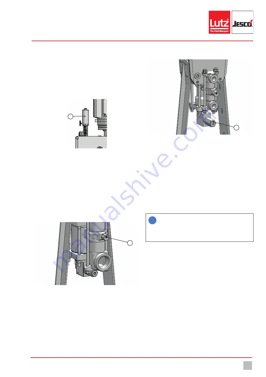
Fig. 10: Stroke length adjustment
The scale on the stroke length adjustment shows the value of the setting
in percentage terms from 0 % (stopped) to 100 % (maximum possible
stroke length).
10.2 Vent the dosing head
To vent the dosing head, it has a vent valve (1). Loosening the screw an-
ti-clockwise can result in gas escaping from the dosing head. The dosing
head should be entirely bubble-free. An additional hose can be clamped
to the lower drill-hole to prevent uncontrolled leakage of the dosing medi-
um during venting. If the dosing head has been completely vented, the
valve must be closed.
1
Fig. 11: Dosing head ventilation
10.3 Controllable safety valve of the dosing head
The MEMDOS KMS pumps are fitted with controllable safety valves as
standard; this protects the dosing pump and the motor against damage
from overloading (e.g. a closed slider in the pressure line).
This is a settable pressure-relief valve located on the lower dosing head
adapter. The pressure-relief valve is set on the factory side to an outlet
pressure of 20 % over the pressure which is specified on the rating plate.
10490000_4
Bild BA MEMDOS KMS LB 14
10.3 Sicherheitsventil des Dosierkopfs
1
Fig. 12: Dosing head safety valve
Perform the following working steps:
1.
Remove the cap of the adjustment screw (1).
2.
To increase the outlet pressure, turn the adjustment screw clockwise
step by step using an Allen key.
3.
To reduce the exhaust pressure, turn the adjustment screw counter-
clockwise.
4.
Replace the cap. Make sure that the (metal) seal is in a good condi-
tion and has been installed in the reverse order.
The pressure in the pump develops at the lower end of the piston. If this
pressure is higher than the set pressure force of the spring in the safety
valve, the valve will open and the hydraulic fluid will be returned to the
pump via the bypass.
i
The chamber in which the safety valve is located must be free
of air and completely flooded with oil, otherwise loud and
strong vibrations can develop when the safety valve has been
triggered. The lowest possible settable pressure is 200 psig
(13.7 bar).


