Maintenance
Maintenance on the ball valve
22
© Lutz-Jesco GmbH 2018
BA-24721-02-V02
Chlorine gas changeover unit
C 7523
Operating instructions
Perform the following working steps:
1.
Loosen the union nuts and remove the three connections. Remove
the O-rings with a blunt tool.
2.
Clean the sealing surfaces with a soft cloth.
3.
Check the display of the contact gauge At atmospheric pressure, it
must display approx. zero. Otherwise, it needs to be cleaned.
4.
Look into the interior of the ball valve. Should soiling be visible, the
ball valve requires cleaning from inside.
5.
Switch the motor to MAN and move the ball valve on the hand lever. It
must revolve evenly around 180° with slight resistance. Otherwise, it
will be necessary to perform maintenance on the ball valve. Switch
the motor to AUTO.
6.
Fit the new O-rings and the connections. The union nuts are tight-
ened by hand.
ü
Small maintenance performed.
11.5 Cleaning the contact gauge
NOTE
Damage to pressure gauges
Pressure gauges are measurement devices which are adjusted by spe-
cialists when manufactured. Pressure gauges that have been disas-
sembled must be tested and readjusted by the manufacturer.
ð
Do not dismantle pressure gauges.
ð
Pressure gauges are highly complicated which cannot be emptied
entirely.
ð
Do not allow any soiling to enter the pressure gauge.
ð
Do not allow any water to enter the pressure gauge.
The maintenance on the pressure gauge restricts itself to a visual check
and the cleaning of the connection.
Precondition for action:
ü
The system has been prepared for maintenance (see 12.3).
ü
The changeover unit is free of stress.
Resources required:
@
PTFE strip
@
Cotton swabs
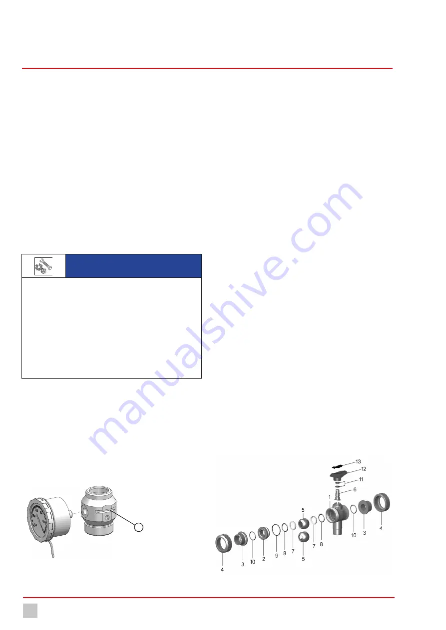
Fig. 19: Remove the pressure gauge
Perform the following working steps:
1.
Separate the pressure gauge cable from the control and pull it out of
the cable guide (1).
2.
Unscrew the pressure gauge from the pressure gauge connection.
Remove the PTFE strip from the thread.
3.
Check the input of the pressure gauge for contamination. Remove the
contamination with isopropyl alcohol. At the same time, hold the
pressure gauge with the connection facing downwards so that soil-
ing cannot fall into the device. Do not use a pointed tool, so that the
protective film on the plate spring is not destroyed.
4.
If the pressure gauge is not immediately reconnected, seal the con-
nection airtight.
5.
Fit the pressure gauge with approx. 5 long PTFE strips.
6.
Return the cable to the control and reconnect it.
ü
Contact gauge cleaned.
11.6 Maintenance on the ball valve
Precondition for action:
ü
The system has been prepared for maintenance.
ü
The changeover unit is free of stress.
Resources required:
@
Ball valve grip (part of the maintenance set)
@
Silicone grease
Perform the following working steps:
1.
Note the switching position of the ball valve.
2.
Remove the four screws below on the motor. Remove the motor from
the wall console.
3.
Remove the four screws above on the ball valve.
4.
Remove the two screws from the side on the pressure gauge con-
nection.
5.
Remove the ball valve and the pressure gauge connection from the
wall console.
6.
Disconnect the ball valve and the pressure gauge connection.
7.
Dismantle the ball valve. The screw-in fitting (2) has a left-hand
thread and the hand lever (12+13) is used as a tool.
Fig. 20: Individual parts of the ball valve
1


