Installing Optional Equipment
3-11
Removing PortMaster Expansion Boards
6.
Place the expansion board into an electrostatic discharge (ESD) bag.
To ship or store the expansion board, ensure that it is in a ESD bag, and cushion it
with foam in a sturdy box.
7.
Using a Phillips screwdriver, reinstall the back cover plates shipped with the
PortMaster.
The PM-2E-30 and PM-2ER-30 are shipped with expansion boards installed and
have no back cover plates. In this case, leave the slot open until the expansion
board is reinstalled.
8.
Replace the top of the PortMaster case, and using a Phillips screwdriver, replace
the screw.
9.
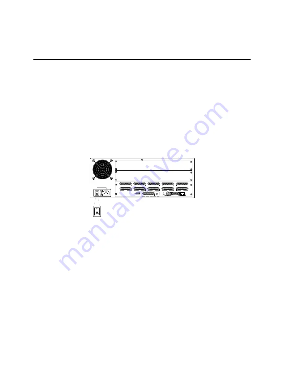
Connect the PortMaster to the power source and turn the power switch on.
S0
S5
S1
S6
S2
S7
RS-232
V.35
S3
S8
W1
S4
S9
ETHERNET
1187 0030
1187-0033
Summary of Contents for PortMaster PM-2
Page 4: ......
Page 8: ...Contents viii Communications Server Hardware Installation Guide...
Page 38: ...Set the Network Address 2 18 Communications Server Hardware Installation Guide...
Page 50: ...Removing PortMaster Expansion Boards 3 12 Communications Server Hardware Installation Guide...
Page 84: ...Ordering Instructions D 8 Communications Server Hardware Installation Guide...
Page 88: ...Index Index 4 Communications Server Hardware Installation Guide...


