Installing the PortMaster
2-9
Connect a T1 /E1 line
5. Connect a T1 /E1 line
Follow these instructions to connect a T1 or E1 line to the W1 port of the PM-2R and
PM-2ER if you have already ordered the service from the telephone company.
Call your local telephone service provider to order T1 or E1. Typically you must pay an
installation charge, a monthly flat-rate service charge, and usage charges.
Note –
The W1 port requires an external clock signal provided by the telephone
company or a channel service unit/digital service unit (CSU/DSU).
Required Equipment
❏
A V.35, RS-530, or X.21 cable
One V.35 cable is included. (See “RS-232 Cable” on page B-10 for pinout
information.)
Procedure
1.
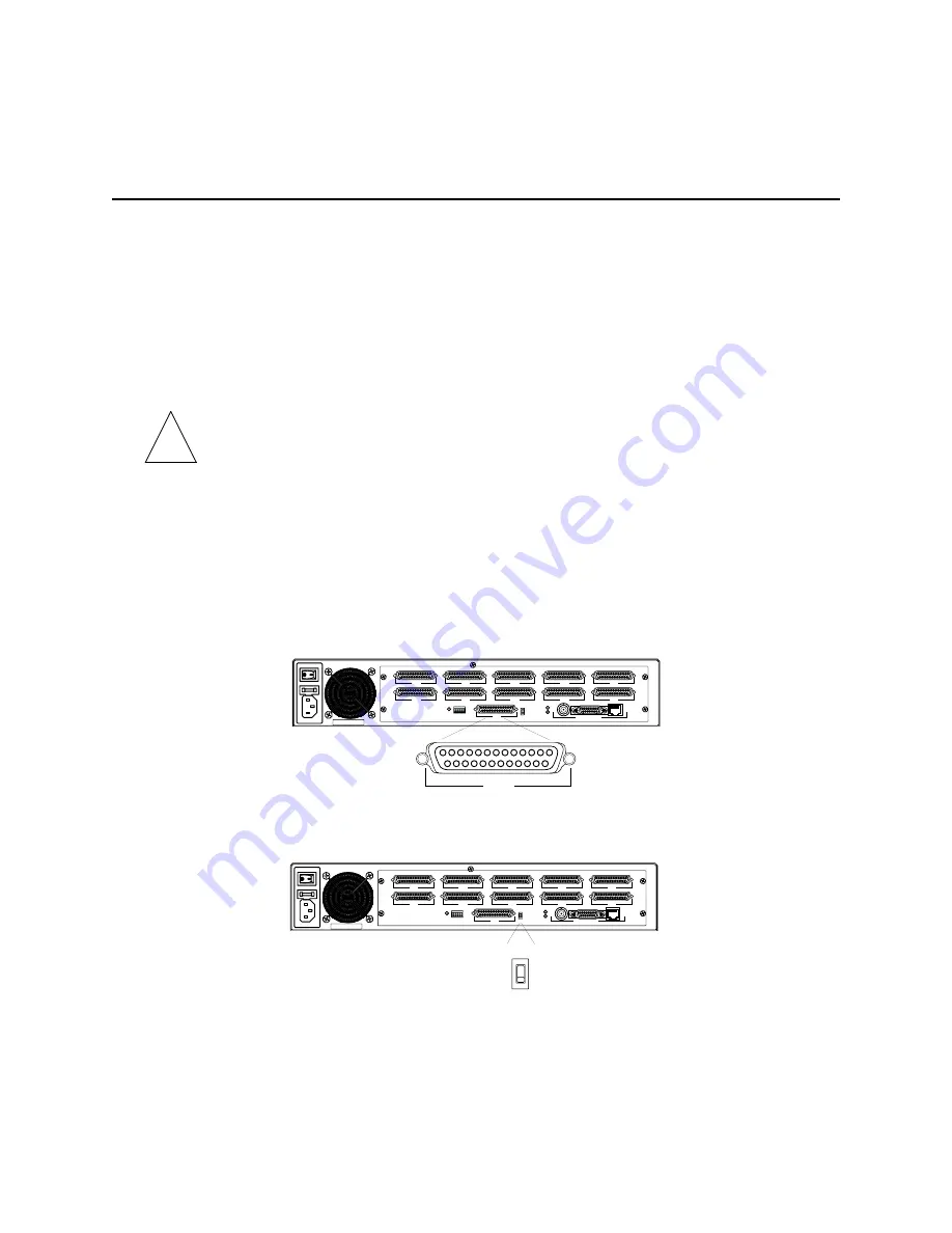
Connect a line to the W1 port (PM-2R shown).
2.
Ensure that the W1 port switch is set to V.35. This is the default (PM-2R shown).
Set the switch to RS-232 for an RS-232 cable.
✍
S0
S5
S1
S6
S2
S7
W1
S3
S8
S4
S9
ETHERNET
RS-232
V.35
W1
1189-0001
S0
S5
S1
S6
S2
S7
W1
S3
S8
S4
S9
ETHERNET
RS-232
V.35
RS-232
V.35
1189-0004
Summary of Contents for PortMaster PM-2
Page 4: ......
Page 8: ...Contents viii Communications Server Hardware Installation Guide...
Page 38: ...Set the Network Address 2 18 Communications Server Hardware Installation Guide...
Page 50: ...Removing PortMaster Expansion Boards 3 12 Communications Server Hardware Installation Guide...
Page 84: ...Ordering Instructions D 8 Communications Server Hardware Installation Guide...
Page 88: ...Index Index 4 Communications Server Hardware Installation Guide...


