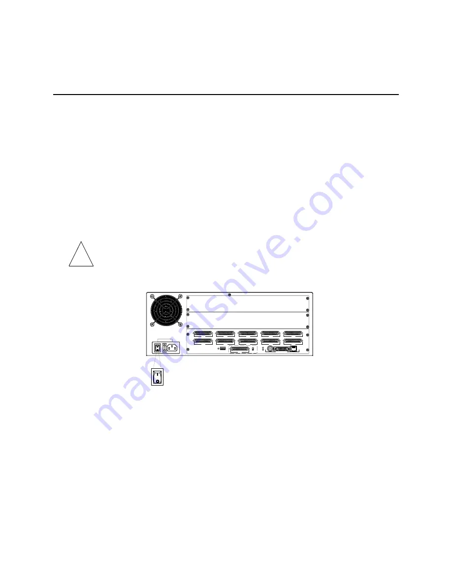
Installing PortMaster Expansion Boards
3-6
Communications Server Hardware Installation Guide
Installing PortMaster Expansion Boards
Follow these instructions to install PortMaster expansion boards on the PM-2E,
PM-2ER, PM-2Ei-10I-U, and PM-2Ei-10I-ST.
Required Equipment
❏
PortMaster expansion boards (See “PortMaster Communications Server Product
Line” on page 1-1 for expansion board compatibility and model information.)
❏
Number 1 Phillips screwdriver
Procedure
Caution –
Wear a grounding strap when handling the internal components of the
PortMaster.
1.
Turn the power switch off and disconnect the PortMaster from the power source.
2.
Lay the PortMaster down on a hard, flat, static free surface.
Ensure that the LEDs are facing you.
3.
Using a Phillips screwdriver, remove the screw from the top center of the
PortMaster.
4.
Remove the lid.
With both hands on the sides of the PortMaster, push the lid firmly until it slides
approximately 3 inches back. Lift the lid up and remove it.
!
S0
S5
S1
S6
S2
S7
RS-232
V.35
S3
S8
W1
S4
S9
ETHERNET
1187_0030
1187_0030
Summary of Contents for PortMaster PM-2
Page 4: ......
Page 8: ...Contents viii Communications Server Hardware Installation Guide...
Page 38: ...Set the Network Address 2 18 Communications Server Hardware Installation Guide...
Page 50: ...Removing PortMaster Expansion Boards 3 12 Communications Server Hardware Installation Guide...
Page 84: ...Ordering Instructions D 8 Communications Server Hardware Installation Guide...
Page 88: ...Index Index 4 Communications Server Hardware Installation Guide...


