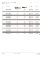
DWDM mounting
....................................................................................................................................................................................................................................
Before you begin
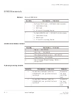
Check the materials before installation.
Installation procedure
............................................................................................................................................................
1
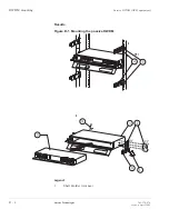
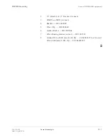
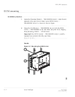
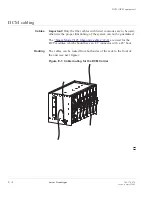
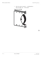
Mount the 19”or 23” mounting bracket (item 2) on the Shell Holder
(item 1) as shown in the next figure. The type of rack frame defines
whether a 19”or 23” mounting bracket is used.
............................................................................................................................................................
2
Mount the Guide Bracket — DC1005064 (item 6) with the assembled
Shell Holder on the rack frame using the Screw, Tapping
Thread-Forming, M6x16 — CC901331421.
............................................................................................................................................................
3
Click the Fiber-Routing Guides (corner) — DC1001518 (item 7) to
Guide Bracket — DC1005064 (item 6) as shown in the next figure for
both configurations.
..........................................................................................................................................................
4
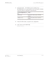
If applicable, connect the grounding cables from the Shell Holder at
the rear side with Screw, Tapping Thread-Forming, M6x16 —
CC901331421 to the grounding point of the rack frame.
IF the Passive DWDM is
positioned
THEN .......
above the the middle of
the rack (Upper part).
use the ground wire (2000 mm [6,562
ft]) — CC848828174
below the the middle of
the rack (Bottom part).
use the ground wire (3000 mm [9,843
ft]) — CC848828182
............................................................................................................................................................
5
Open the Shell Holder Unit by pushing simultaneously at both sides
the buttons on the front door.
............................................................................................................................................................
6
Slide the passive DWDM (item 3) into the Shell Holder until the
PWDM locks. It can be released by pushing the buttons on each side
simultaneously.
Passive DWDM (OEM equipment)
....................................................................................................................................................................................................................................
D - 4
Lucent Technologies
365-374-074
Issue a, April 2002

