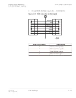
Point on
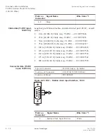
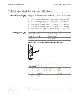
Connector
Signal Name
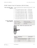
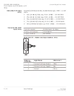
V.11
G.703
11
Output-Data
Negative
Tx-Data
Negative
Output
Tip
12
Ground
13
Input-Clock
Negative
14
Input-Frame
Negative
15
Input-Data
Negative
Rx-Data
Negative
Input Tip
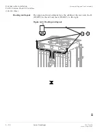
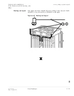
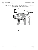
Routing and layout
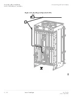
Figure 4-21 User byte layout and routing
External cable installation
User byte interfaces (G.703/V.11)
System cabling and final assembly
....................................................................................................................................................................................................................................
365-374-074
Issue a, April 2002
Lucent Technologies
4 - 3 5


