LTV LTV-ISDNO20-EM2 User Manual Download Page 40

Chapter 6 Remote Configuration


Week schedule


Set the alarm time from Monday to Sunday for alarm everyday in one week.


Note:  The  lengthwise  means  one  day  of  a  week;  the  rank  means  24  hours  of  a  day.  Mouse 
clicks on the pane to set the alarm hours. Green means selected area. Blank means unselected 
area.


"Add": add the schedule for a special 
day. "Erase": delete holiday schedule.


Day schedule


Set alarm time for alarm in some time of a special day, such as holiday.


1.


Select a date at the "Date" pull down list, press "Add" button to add that date to the list box 

on the right side and then move the scroll bar to set the schedule of that day.  


2.


Select a date in the list box on the right side, and press "Erase" to remove the schedule on 

that day.  

 
Press the "Save" button to save the settings.  


Note: Holiday schedule is prior to Week schedule. 


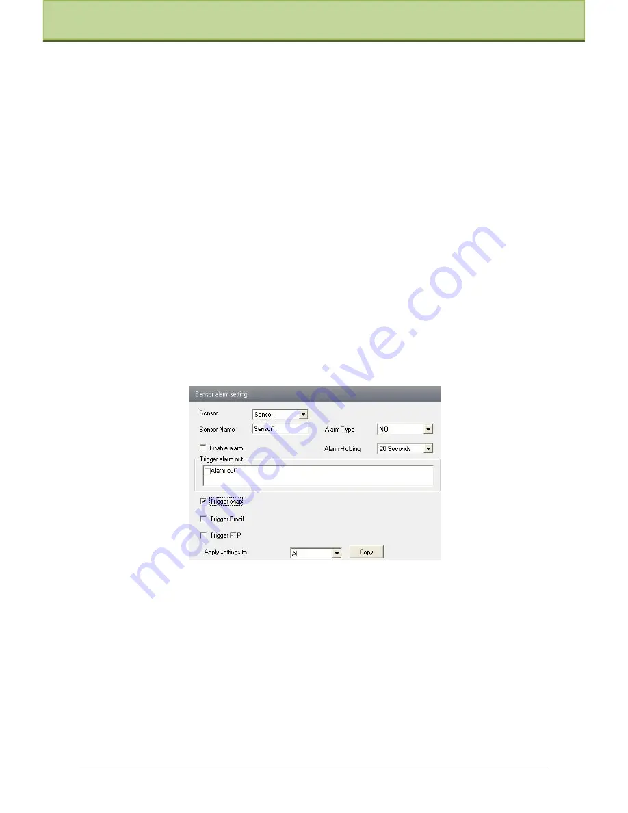
6.4.4  Alarm Input Trigger


1. Enter ―Alarm Configuration"

"Alarm Input Trigger" to see a screen as shown below:


2.


Select the sensor at the "Sensor" pull down list and set the sensor name and alarm type: NO 

and NC.  


3.


Enable alarm and select alarm holding time.  


4.


Set  alarm  trigger  options.  The  setting  steps  are  the  same  with  that  of  motion  detection 

trigger. Please refer to motion detection trigger chapter for details.  


5.


Apply settings to all by clicking ―Copy‖ button, which can quickly set the same settings 

for all sensors.  


6.4.5  Alarm Input Schedule


Enter into ―Alarm Configuration"

―Alarm Input Schedule‖ as shown below:


IP-CAMERA User Manual - 

29


Summary of Contents for LTV-ISDNO20-EM2

Page 1: ...IP Speed Dome Camera User Manual Please read this instruction carefully for correct use of the product and preserve it for reference purposes...

Page 2: ...ual is subject to change without prior notice and the updates will be added into the new version of this manual This manual may contain several technically incorrect places or printing errors please f...

Page 3: ...dirt for hard contamination use neutral detergent Any cleanser for high grade furniture is applicable Avoid aiming the camera directly towards extremely bright objects such as sun as this may damage...

Page 4: ...troduction 1 Chapter 2 Installation 2 Chapter 3 IE Connection 6 3 1 1 A c c e s st h r o u g h I P Tool 6 3 1 2 D ir e c tl y a c c e s st h r o u g hIE 7 Chapter 4 Remote Preview 10 4 1 Remote Previe...

Page 5: ...4 3 Snap 12 Chapter 5 Menu Setup 13 5 1 System Setup 13 5 1 1 A u t o P T F l i p 13 5 1 2 T e m p e r a t u r e D i s p l a y 14 5 1 3 Z o o m D i s p l a y 14 5 1 4 L an gu ag e 14 5 1 5 H 14...

Page 6: ...o m e P o s i t i o n S e t u p 5 1 6 V i e w P T Z V e r s i o n 14 5 2 Camera Setup 14 5 2 1 C a m e r a C o n t r o l15 5 2 2 I15...

Page 7: ...m a g e S e t u p 5 2 3 F o c u s N e a r L i m i t16 5 2 4 Z o o m S p e e d 16 5 2 5 D Z oo m 16 5 2 6 V i d e o F o r m a t17 5 3 Dome Function 17...

Page 8: ...5 3 1 P a t r o l S e t u p 17 5 3 2 T a s k S e t u p 18 5 3 3 A l a r m S e t u p 19 5 3 4 T r a c e S e t u p 20 5 3 5 D a y N 20...

Page 9: ...i g h t 5 4 Load Default 21 Chapter 6 Remote Configuration 22 6 1 System Configuration 22...

Page 10: ...n Area 27 6 4 2 Motion Detection Trigger 27 6 4 3 Motion Detection Schedule 28 6 4 4 Alarm Input Trigger 29 6 4 5 Alarm Input Schedule 29 6 4 6 Alarm Out 30 6 5 Network Configuration 30 6 5 1 Port 30...

Page 11: ...Search 42 Chapter 8 Mobile Surveillance 44 8 1 Network Configuration 44 8 2 By Phones with iPhone OS 44 8 3 By Phones with Android OS 54 Chapter 9 IP Tool 59 Chapter 10 Q A 62 Chapter 11 Specification...

Page 12: ...agement software short for CMS This CMS centralizes all devices together via internet or LAN and establishes a sound surveillance system to realize unified management and remote operation to all devic...

Page 13: ...the body from the base tray as shown in Fig 1 Loosen three screws and separate the tube from the base tray as shown in Fig 2 X 3 M5 0 15 Fig 1 Fig 2 Step 2 Install the frame Fix the frame on the wall...

Page 14: ...the guide pins match with the guide holes Turn the camera clockwise to fasten as shwon in Fig 8 Fasten three screws as shown in Fig 9 Three Screws OPEN LOCK Fig 8 Fig 9 Step 4 Remove the protector Loo...

Page 15: ...ween the alarm input port ALM In x x 1 4 and the common port ALM COM c Disconnect the voltage between alarm input ports ALM IN1 4 and common port ALM COM to cancel the alarm Alarm Output a Supports 1...

Page 16: ...m CD and then double click Setup exe file to pop up installation wizard Install the software according to the prompts in the wizard After you complete the installation you will see the CMS and IP Tool...

Page 17: ...IP Tool to modify the network of IP Cam Then double click the icon on the desktop to run this software as shown below After starting IP Tool and clicking the IP Cam in the list you can check the infor...

Page 18: ...ht click the IP address and select browse with IE Then the system will pop up the IE browser to connect IP Cam as shown below IE browser will auto download the Active X control After finishing the ins...

Page 19: ...y selecting Property as shown in the right figure Select Internet Protocol TCP IP in the General tabs Then click Properties to manual input network address information of the PC in the pop up window R...

Page 20: ...left hand Step 2 Enter into System Configuration Network configuration IP configuration to change IP address as shown in the picture on the right hand Port Setup IP Setup Step 3 Enter into the router...

Page 21: ...layback Zoom in Snap Zoom out Talk Full screen Open close audio Right click mouse to appear a pull down list Stream 1080P 720P VGA QVGA Turn off the live Click this item to close the current live prev...

Page 22: ...t to stop rotating the dome Drag the scroll bar to adjust rotating speed of the dome Focus button Click button to have long focus and click to have short focus so that you can adjust the image clearly...

Page 23: ...and then click Snap icon as shown below To snap multiple pictures Step 1 Select the picture number from frame pull down list box such as 2 Step 2 check Title and Time to show capture title and time on...

Page 24: ...p Select System Setup by clicking or button and then click button to enter into System Setup as shown below 5 1 1 Auto PT Flip Select Auto PT Flip and then click to setup the menu on the right click o...

Page 25: ...er Main Menu System Setup Home Position Menu as shown below The setting steps Enable the home position function and select the preset which should be set in advance Then select delay time range from 0...

Page 26: ...BLC function is enabled HLC If enabled the darker part will be lightened while the highlight part will be suppressed HLC Level Range from 00 20 3D DNR Reduce the noise of the brightness and chroma of...

Page 27: ...he operation is effective only when the white balance is in manual mode MWB Blue Gain The operation is effective only when the white balance is in manual mode Day Night Mode Three options Auto Day Nig...

Page 28: ...is interface by programming presets in patrol list in advance the system will keep calling those presets at the set time in sequence when executing patrol command so that non stop monitoring between m...

Page 29: ...g 5 3 2 Task Setup Enter Main Menu Dome Function Task Setup Menu as shown below By dividing 24 hours into several periods and appointing different commands for each period the camera system will autom...

Page 30: ...reset that the system will call on IN1 alarm When the first channel alarm is triggered the camera will automatically monitor the selected preset The steps to set IN2 Alarm IN3 Alarm and IN4 Alarm are...

Page 31: ...up Menu as shown below This function is used to memorize the operation to PTZ zoom and focus so that repeating operation progress can be realized by running trace Setting Steps Step 1 Choose the trace...

Page 32: ...Day Night Mode will be disabled in image setup if enabling this function 5 4 Load Default There are three menus including master reset master clear and system reboot Master Reset Restore the camera st...

Page 33: ...6 1 1 Basic Information In the Basic Information interface you can setup the device name and check the relative information of the server Setting steps 1 Clicking the Config icon will appear the menu...

Page 34: ...stem Configuration SD Card as shown below The first time you used the SD card you should click Format SD card Click Eject card to stop writing data to SD card Then the SD card can be ejected safely No...

Page 35: ...nable the image mirror and image overturn function 6 Repair bad pixel by clicking Start Repair button 7 Press the Save button to save the settings 6 2 2 Video Stream Enter into Video configuration Vid...

Page 36: ...stop rotating the dome Focus button Click button to have long focus click button to have short focus Zoom button Click button to zoom in the locale picture click button to zoom out the locale picture...

Page 37: ...cruise and click Modify button to pop up a window as below You can add 16 presets into this cruise at most Select the preset and click Modify to change the preset Click Delete button to delete this pr...

Page 38: ...n Detection Area 1 Enter into Alarm configuration Motion Detection Area to see an interface as shown below 2 Move the Sensitivity scroll bar to setup the motion trace sensitivity 3 Check Add press the...

Page 39: ...checkbox is checked Email address shall be set first in the Mail config interface the triggered snap pictures and event will be sent into those addresses Trigger FTP If Uploading picture is checked t...

Page 40: ...2 Select a date in the list box on the right side and press Erase to remove the schedule on that day Press the Save button to save the settings Note Holiday schedule is prior to Week schedule 6 4 4 Al...

Page 41: ...guration Alarm output as shown below 2 Select alarm holding time and alarm name at the Alarm out and Alarm holding time pull down list box respectively 3 Press the Save button to save the settings 6 5...

Page 42: ...address please choose one of options for your requirements 3 Use the following IP address display the IP address subnet mask gateway and DNS of the device 4 PPPOE Manual input the user name and passw...

Page 43: ...above mentioned server IP server port and device ID in the responding boxes Click save button to save the settings 6 5 4 IP Notify 1 Enter into Network Configuration IP Notify to see a tab as below 2...

Page 44: ...p net www meibu com www dyndns com www no ip com www 3322 org and mintdns type User name Log in the website of domain name supplier Password Log in the website of domain name supplier 1 Apply the Doma...

Page 45: ...is set in 1 Register in the Web According to the example above password is 123456 Note If the connection fails press the INFO button Now the system will display DDNS NONE Then you need to check netwo...

Page 46: ...Now you can see the live image in the VLC player 6 5 7 UPNP Enter into Network Configuration UPNP interface as shown below Select Enable UPNP and then input friendly name Enable UPNP Double click the...

Page 47: ...ame of sender 4 Select the secure connection type at the Secure Connection pull down list according to user actual needs 5 Receival email address list add email address into the list 6 Receival email...

Page 48: ...arameters and instructions of FTP configuration Parameter Meaning Server name The name of the FTP server Server address The address of the FTP server Port The port number of the FTP server User name T...

Page 49: ...s to modify password and physical address in the user configuration list box 2 Clicking Modify button will pop up Modify user dialog box as shown below 3 Input original password of this user in the pa...

Page 50: ...connecting our device through other companies monitoring platform software such as Hikvision Axxon Milestone etc 6 6 3 Security Configuration Enter into Advanced Configuration Security Configuration...

Page 51: ...e Enter into Advanced configuration Configure Backup Restore Interface Import Export Configuration User can import or export the setting information from PC or to device 1 Click Browse to select save...

Page 52: ...server firmware button to start upgrading the application program 3 The device will restart automatically 4 After you successfully update the software click OK button to close IE and then re open IE...

Page 53: ...the SD card 1 Set time Select date in the calendar and choose the start and end time 2 Choose event Motion or Sensor 3 Click Search button to search the picture 4 Double click a filename or select a f...

Page 54: ...tton to select the save path of the picture files on PC for saving all pictures 5 Fit size The picture will fit on screen by clicking this button 6 Actual size Click this button to display the actual...

Page 55: ...Apply You can enter Main Menu Information Network tab to see the IP address If you want to utilize dynamic domain name please apply for a domain name in a DNS server supported by the device If you ha...

Page 56: ...s shown in the figure on the left Step 4 Input iTunes Store password and then click OK The software will be installed automatically Install Software through PC Step 1 Install iTunes store in PC and th...

Page 57: ...Chapter 8 Mobile Surveillance Step 3 Search SuperLivePro and select it Step 4 Click Download button Step 5 Input username and password IP CAMERA User Manual 46...

Page 58: ...Chapter 8 Mobile Surveillance Step 6 Synchronously apply SuperLivePro software to iPhone iPad SuperLivePro Instruction 1 Login IP CAMERA User Manual 47...

Page 59: ...e login account and password of the device The default account is admin and the default password is 123456 Step 3 Click Login button to access the device 2 Main Interface There are many buttons in the...

Page 60: ...ck this button to open close the audio of this channel Open Close talk Click this button to pop up the servers which support talk function Select the device to start talking Set video parameter button...

Page 61: ...reen mode in accordance with the channel number of the device Note The maximum number of channels which can be connected are nine after login Click Screen mode button to select channel as shown in Fig...

Page 62: ...anagements and preview come true Step 1 Click to enable CMS function When this icon turns green it means this function is enabled Step 2 Click to choose channel as shown in the right picture After you...

Page 63: ...ck the device name to extend channel Enlighten the channels to save favorite channels as shown in the following picture on the left Step 2 Return to the main interface and click button to play the fav...

Page 64: ...r 8 Mobile Surveillance 8 Image View Click button to view the captured pictures 9 Settings Interface In this interface you can configure the local settings 10 Information Interface IP CAMERA User Manu...

Page 65: ...e Surveillance In this interface you can view system information 8 3 By Phones with Android OS Software Installation Step 1 Run Play Store or Google market program Step 2 Search SuperLivePro IP CAMERA...

Page 66: ...the sever column The port should be HTTP port of your device The default http port of the device is 80 If you have changed your http port please enter the new port here For example 210 21 228 183 89...

Page 67: ...veillance Live View PTZ Snap Record Talk Enable disable audio Hide Playing favorite channel Image View The first picture The previous picture Next picture The last picture Zoom in Zoom out Delete IP C...

Page 68: ...ick Playback in the main menu interface to enter playback interface Then choose the channel you want to playback This will take you to see the record file Click this file to play Pause Play Stop Forwa...

Page 69: ...in the server column Modify Server Click button to modify the server information Delete Server Click button to delete the server information Settings In the main menu interface click Settings to enter...

Page 70: ...ware Then the device can be searched if the device can t be searched please check whether the PC and the device connect to the network or not Click the device to check its detail information as shown...

Page 71: ...pgrading the progress bar will display as below When upgrading please do not disconnect PC and the device and make sure the power is on After finishing upgrading a massage box will pop up as below Cli...

Page 72: ...er that click Update Kernel button to start updating When upgrading do not disconnect PC to device and make sure the power is on The update progress bar will display as below After finishing upgrading...

Page 73: ...rect port number 4Exclude the above reasons Recover default setting by jointing the default line and GND line Note default IP 192 168 226 201 mask number 255 255 255 0 3 Q IP tool cannot search device...

Page 74: ...k the statues of wireless router Please make sure the router is open Check the router and the device port Please make the router setup is matched with device port 7 Q How to do when the device is unab...

Page 75: ...et 255 Patrol 8 Trace 4 Time Task 8 Scan 2 Alarm Input 4 CH Alarm Output 1 CH Resolution 1920x1080 1280x720 640x480 320x240 160x120 Frame Rate Max 30 fps Storage SD card local storage network remote s...

Page 76: ...set Call NO 93 Preset Run patrol 3 Call NO 94 Preset Run patrol 4 Call NO 95 Preset OSD menu Call NO 97 Preset Enable random scan Call NO 99 Preset Enable P P SCAN Set NO 91 Preset Set random scan tas...

Reviews: