


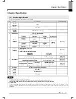


Chapter 2 Specification
2-4
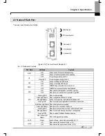
▶
Log
Switch
In case of reading Log in communication module and needing to store the Log, if you push it for more than 1 second, it is
stored into Flash area from Memory area. The Log in the memory area is the one erased when power is supplied again
and the Log in Flash area is the one which is maintained when power is supplied again.
▶
IP
Set-up Switch (1~90, 94~99)
When IP address has not been inserted via XG5000 within 10 seconds after power was supplied, IP is set up as
‘192.168.250.switch value’.
▶
IP Set-up Switch (91, 92, 93)
This switch is designed for setting up the inside of communication. If you change it
arbitrary, it may cause problems.
▶
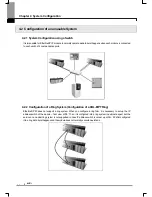
IP Set-up Switch (99)
This switch functions to configure the system into a ring form and when set-up is not finished, normal operation is
impossible. It is possible to form a ring system in terms of appearance by supporting 2 connectors but actual ring system
is not supported.
Summary of Contents for XBL-EIPT
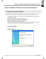
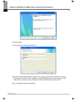
Page 53: ...Chapter 5 Installation of Software and communication Parameters 5 18 ...
Page 98: ...Chapter 7 Diagnosis Function 7 11 Figure 7 3 4 FlashArea Log Screen of System Log ...
Page 106: ...Chapter 7 Diagnosis Function 7 19 Fig 7 4 9 Remote 2 connection directly via Ethernet ...
Page 119: ...Appendix A 12 A 3 External Dimension Dimension Unit mm XBL EIPT ...