


Chapter 7 Diagnosis Function
7-17
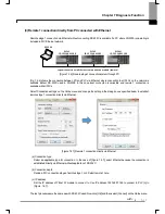
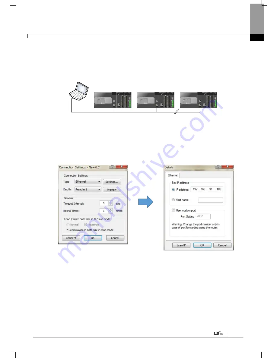
(3) Remote 1 connection directly from PC connected with Ethernet
Remote stage 1 connection via Ethernet without connecting RS-232C is available if a PC where XG5000 is operating is
included in PLC Ethernet network.
PLC#1
IP: 192.168.91.188
PLC#2
IP: 192.168.91.189
PLC#N
IP: 192.168.91.190
XG5000
Logical connection via Ethernet communication module (remote)
[Figure 7.4.6] Remote stage 1 connection system through PC
[Fig. 7.4.6] shows the connection between PC and PLC via Ethernet, where connection to all PLCs on the network is
available without RS-232C used in XG5000. In this case local connection is omissible and remote 1 connection is
available with all PLCs
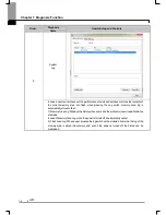
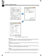
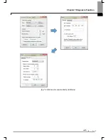
Select ‘Connection settings’ on the Online menu and change the setting in the dialog box as specified below to establish
remote stage 1 connection directly via Ethernet.
[Figure 7.4.7] Remote 1 connection directly via Ethernet
(a) Connection
type
Select an applicable type for connection. In the case of [Figure 7.4.7], select Ethernet because the connection is
established directly via Ethernet without application of RS-232C.
(b) Connection depth
Decide a PLC connection stage of remote stage 1 or 2. Select remote 1 here.
(c) IP address
Set the IP address of FEnet I/F module to connect to. Use IP address, 192.168.91.189 to connect to PLC [n] in
[Figure. 7.4.7].
The rest procedures are the same as with RS-232C used. Now click [OK] and then select [Connect] on the Online menu.
Summary of Contents for XBL-EIPT
Page 53: ...Chapter 5 Installation of Software and communication Parameters 5 18 ...
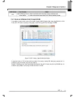
Page 98: ...Chapter 7 Diagnosis Function 7 11 Figure 7 3 4 FlashArea Log Screen of System Log ...
Page 106: ...Chapter 7 Diagnosis Function 7 19 Fig 7 4 9 Remote 2 connection directly via Ethernet ...
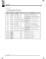
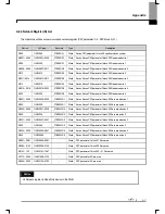
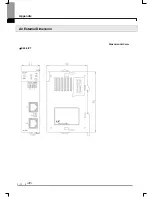
Page 119: ...Appendix A 12 A 3 External Dimension Dimension Unit mm XBL EIPT ...