background image


Atom Operator Manual

Layout


LSC Lighting Systems (Aust) Pty. Ltd.

6


3.0 LAYOUT

 
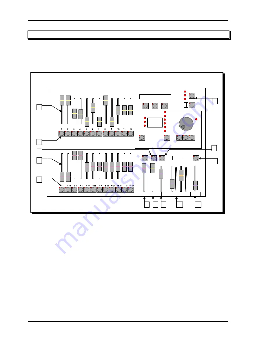
 The front panel of the Atom is divided into two main areas;

 The 

fader

 section on the left.

 The 

mastering

 and 

recording

 section on the right.


Note: The size of the fader bank area varies depending upon the model, as it provides a fader for every
channel (24 or 48). The mastering and programming section is identical for both models.


FUNCTION

STOP


STEP

SOLO

ASSIGN

(YES)

 (NO)

EDIT

SCENE CHASE

COPY

RECORD

SCENE

CHANNEL

CHASE

DIMMER

STEP

RATE (BPM)

OUT(S)

IN(S)

LEVEL

(ADD STEP)

(DELETE STEP)

(END CHASE)

PAGE

MODE

PRESET

WIDE

SCENE

 FREEZE

>

<

SOLO

ASSIGN

PREVIEW

EDIT

MASTERS

SECS

LEVEL

TIME

O

 ADD

 KILL

GRAB

R           Y

FUNCTION:

PRINT

1:1

PATCH

SOFT

PATCH

CLEAR
PATCH

HELP

(VIDEO)

DISK PREFS

RESET

BASS

LEVEL

IN

OUT

120

120

0

0

 1

2

 3

 4

5

 6

 6

8

 7

 9

10

 11

12


Front panel layout of an Atom 12/24.

 Many of the keys listed below perform more than one function. The current function depends upon what the
operator is doing at the time. Each of these different functions is described under the relevant key below.


1. YELLOW PRESET FADERS

 Control the levels of channels 1 to 12 (24) respectively.


2. YELLOW PRESET MASTER

  Controls the overall level of the Yellow preset faders (the low channels).

  In WIDE Preset mode, it controls the overall level of the single wide preset consisting of the Yellow preset

faders (the low channels) and the Red preset faders (the high channels).


3.  MODE KEY

 Selects the current function for the RED preset faders. The choices are;

 PRESET 

mode.

  WIDE Preset mode.

 SCENE 

mode.


Note; In WIDE Preset mode, both the WIDE and PRESET indicators are lit.


4. RED PRESET FADERS

 The Red bank of faders have different functions depending upon the current “MODE” of the Atom as selected
by the MODE key.

Summary of Contents for Atom 12/24

Page 1: ...oftware Version 1 21 January 2002 L S C Lighting Systems Aust Pty Ltd A C N 090 801 675 7 University Place Clayton Victoria 3168 Australia Tel 61 3 9561 5255 Fax 61 3 9561 5277 Email info lsclighting...

Page 2: ...the RATE rotate the edit wheel To BASS STEP the chase Sound To Light set the rate below 0 BPM See also BASS LEVEL below To change the FADE between steps press FUNCTION until IN OUT light then rotate t...

Page 3: ...ENE ________________ 21 8 6 DELETING A SCENE________________ 21 9 0 CHASES________________________22 9 1 OVERVIEW _______________________ 22 9 2 RECORDING CHASES ______________ 22 9 3 REPLAYING CHASES...

Page 4: ...es 9 pages of memory for the Submasters Separate In up and Out down fade times 0 to 120 seconds Scene Fade Times can be derived from the Time Faders or from Memory Solo level fader with associated Add...

Page 5: ...is better than cure When connecting any devices to the Atom make sure that all connections are correct before switching on the power If any doubt exists obtain the assistance of qualified personnel If...

Page 6: ...panel below their S A keys For example Press and hold FUNCTION tap S A PRINT refers to the SOLO ASSIGN key in the bottom left corner of the Atom Some Yellow preset solo keys have hidden secondary func...

Page 7: ...s settings are described in Appendix A at the end of this manual Hint The Atom provides control for 24 48 channels however by utilising the Atom s softpatch functions you can control any dimmer output...

Page 8: ...0 0 1 2 3 4 5 6 6 8 7 9 10 11 12 Front panel layout of an Atom 12 24 Many of the keys listed below perform more than one function The current function depends upon what the operator is doing at the t...

Page 9: ...s a number that indicates the channel that the fader and S A key control Between each fader in the Red fader bank and its associated S A key are two numbers In PRESET mode the LARGER font indicates th...

Page 10: ...LL mode when a SOLO ASSIGN key is pressed the channels that are being flashed will come on at the level of the SOLO level master and the normal output of the Atom will be killed blacked out leaving on...

Page 11: ...N time and a second press whilst the IN time is still displayed will change the display to the OUT time When editing it toggles through the various functions indicated on the column of LEDs above it I...

Page 12: ...t master RED GRAB ADD KILL YELLOW PRESET RED PRESET PRESET MASTERS YELLOW 1 2 3 4 5 6 7 8 9 10 11 12 1 2 3 4 5 6 7 8 9 10 11 12 CHANNELS 1 12 CHANNELS 1 12 OUTPUT Simplified block diagram of a 12 24 A...

Page 13: ...scenes as you can utilise all channels to create your scenes See Scene Mode below DISADVANTAGE You do not have a second preset on which to create the next look although you can perform crossfades to...

Page 14: ...y setting the positions of the individual channel faders of the yellow preset The brightness of the red indicator in each channels S A key also gives you a visual indication of that channels intensity...

Page 15: ...der to 5 seconds Hint To check the current time settings of the Time faders press the FUNCTION key One press momentarily shows the IN time and a second press whilst the IN time is still displayed will...

Page 16: ...the Edit wheel to set the OUT time to 10 seconds To complete the recording give the scene a number by pressing S A 2 The display briefly displays 1 02 the recorded Page Scene number Note When the RECO...

Page 17: ...or change pages in Scene mode the chases and or scenes in the selected page are assigned in order to their respective Submasters 1 to 12 24 To replay a chase ensure that you are in Scene mode and that...

Page 18: ...24 Scenes or Chases in each page In any mode when a RECORD key is pressed a Scene or Chase may be recorded or copied into any number in any page In Scene mode any one of the 9 pages may be selected as...

Page 19: ...to execute a fade in exactly 3 seconds the master must be moved from bottom to top in less than 3 seconds If you take longer than 3 seconds to move the master then the fade will keep pace with the fa...

Page 20: ...record a scene you may select and set each parameter Page IN time and OUT time for the scene You complete the recording by giving the scene a number via the Red S A keys You can complete the recording...

Page 21: ...look record it as a scene and immediately create the next look If this is the case you may use the rapid recording method described above and then when time permits edit the scenes to set the desired...

Page 22: ...sity reflects the levels of those channels in the scene The FUNCTION key flashes to show that it is active It allows you to read and edit actual channel levels and fade times for the scene see below R...

Page 23: ...the scene S A keys to select the source page and scene number When the source scene number S A key is pressed the display will briefly scroll Scn x yy page scene number to Use the PAGE key and the sc...

Page 24: ...ore details Up to 13 25 simultaneous chases may be running at the one time Chases may be run in any of the following modes FORWARD REVERSE BOUNCE Auto reverse at each end SINGLE SHOT Run once and stop...

Page 25: ...f the look that you add is not correct the last step may be deleted by pressing RECORD DELETE STEP HINT If a step other than the last step is incorrect complete the recording then Preview Edit the cha...

Page 26: ...f the chase and edit the copy See COPYING A CHASE later in this chapter for details Rate To change the Rate of a chase Preview Edit the chase above then rotate the Edit wheel If the rate is set higher...

Page 27: ...rcentage the Edit indicator flashes slowly If the fade is restored to its original value the edit indicator remains steady Hint Fading chases are very useful for controlling moving fixtures Modes Dire...

Page 28: ...press PREVIEW Press PAGE repeated presses until desired page is shown or hold PAGE tap S A page number As each page is selected all Submasters containing chases in that page will flash rapidly Submast...

Page 29: ...hase may be copied to any other chase or page number To copy a chase press RECORD COPY The display reads CPY Use the PAGE key and the red S A keys to select the source page and chase number When the s...

Page 30: ...any of the channel faders or Submasters To enable the next look to be created take a Grab of the output fade up the Grab master to full and then fade down the Preset masters The look is maintained by...

Page 31: ...Recording A Chase On The Grab Master To record a Chase in the Grab master press RECORD CHASE S A Grab master Each step of a Chase consists of a snapshot of the output which is taken when that step is...

Page 32: ...3 Solo Fader The SOLO fader sets the percentage level at the output of the SOLO section for all channels when they are solo ed For individual channels the Solo fader sets the level of any soloed chann...

Page 33: ...r of the Atom in the UP position 1 To 1 Patch To select a fixed 1 to 1 patch Press and hold FUNCTION Tap S A 1 1 PATCH Release FUNCTION The display asks Select 1 to 1 Patch Press YES The display confi...

Page 34: ...S the patch is deleted and the display will ask Patch d to c your new channel selection If you press YES the new channel is patched to the dimmer If you press NO the old patch is simply deleted When f...

Page 35: ...masters or Yellow preset master and Grab master to be performed with the fader knobs side by side held with one hand To invert the operation of the Yellow Preset master locate the DIP switch on the re...

Page 36: ...by selecting COURIER size 10 as the display font The example of Courier below shows that all the text is displayed with correctly aligned columns because all Courier characters have the same width Pa...

Page 37: ...select NO the function is aborted and the original setting is retained SETTING THE TERMINAL OR COMPUTER If you are using a Terminal refer to the documentation that came with your terminal and choose t...

Page 38: ...The display asks Save Press NO The display asks Load Press YES The display asks for a Show number from 1 to 9 S Rotate the Edit wheel to select the number To load the show press YES Loading a show fr...

Page 39: ...tents Refer to the PRINT section in the UTILITIES chapter 14 4 Desk Lamp Connector And Fuse The optional halogen goose neck desk lamp is connected to this socket The socket provides both power and mou...

Page 40: ...Up to 1 000 metres per cable run Feeds are easily distributed via DMX512 splitters and or DMX loop through Multiple units may be set to the same address For example By setting several dimmers to the...

Page 41: ...n numerical order If a dimmer further along the line is to be also controlled by say channel 13 then simply set its address switch to channel 13 The end of the DMX line is terminated 120 to prevent th...

Page 42: ...4 24 DB 15 Pinouts The following diagram shows one DB15 module with its two connectors as viewed from the rear of the Atom ANALOG OUTPUT 8 1 2 3 4 5 6 7 15 14 13 12 11 10 9 8 1 2 3 4 5 6 7 15 14 13 12...

Page 43: ...Channel 1 1 Channel 7 1 Channel 13 1 Channel 19 2 Channel 2 2 Channel 8 2 Channel 14 2 Channel 20 3 Channel 3 3 Channel 9 3 Channel 15 3 Channel 21 4 Channel 4 4 Channel 10 4 Channel 16 4 Channel 22 5...

Page 44: ...t preset These alternate crossfades from preset to preset form the standard operation of a manual preset lighting board Preset Master A Preset master controls the overall level of all the channels in...

Page 45: ...PLAYING 15 24 SINGLE SHOT 26 CONTROLLING LIGHTS 12 COPY CHASE 27 SCENE 21 CROSSFADES DIPLESS 42 MANUAL 12 17 TIMED 17 D DELETE CHASE 27 SCENE 21 STEP 27 DESK LAMP 37 DIAGNOSTICS 36 DIP SWITCHES 37 DIP...

Page 46: ...ESET 12 SYSTEM 33 TOTAL 33 REVERSE KEY 9 RS 232C 37 S SCENE MASTERS 42 SCENE MODE 11 19 24 SCENES 18 42 BLIND RECORDING 19 COPYING 21 DELETING 21 EDITING CHANNEL LEVELS 20 EDITING FADE TIMES 20 FADE T...

Reviews: