Chapter 2 System Configuration
2-2
iXP2-1200A
5
7
8
9
10
6
11
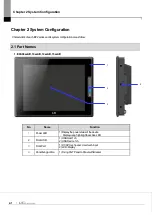
No.
Name
Function
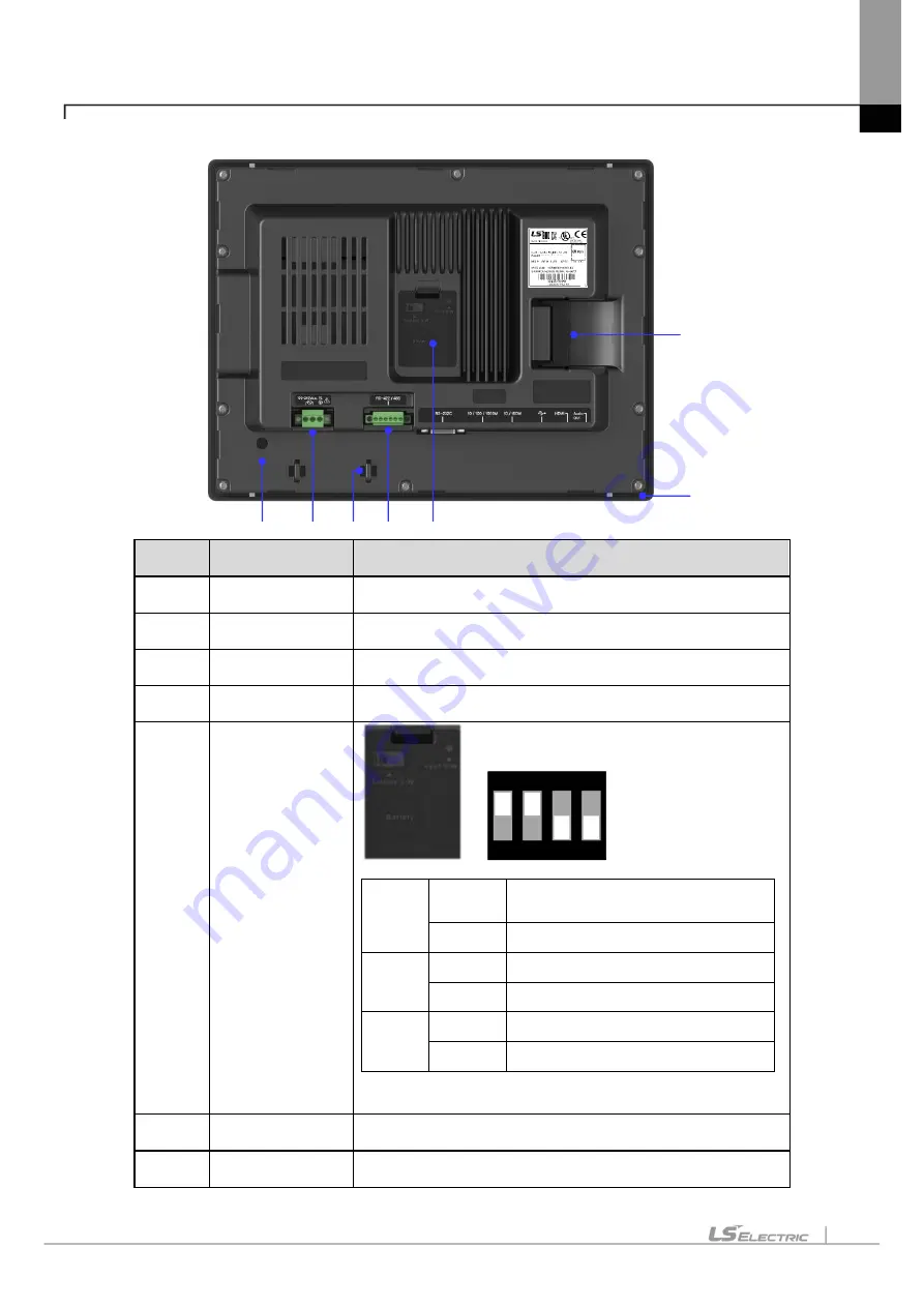
5
PE connector
PE connection
6
Power Connector
Power and PE connections
7
Cable fixing hole
Fixing Cables
8
RS-422/485 connector
RS-422/485 (COM3): PLC / Control device communication
9
Battery cover,
Reset switch,
Backup battery,
Setting switch
ON
1
2
3
4
A
B
<Setting switch>
No. 1/2
A Side.
RS-422/485 termination resistance On
(Default)
B Side.
RS-422/485 termination resistance Off
No. 3
A Side.
O/S Download
B Side.
Nand Flash booting(Default)
No. 4
A Side.
Backup Battery On
B Side.
Backup Battery Off(Default)
<Reset S/W>
System reset switch. Pressing the switch will reset the system.
10
SD Card
Logging / Recipe / Alarm / Project data backup and transfer
11
Gasket
Protecting from water and dust
Summary of Contents for iXP2 Series
Page 1: ...Human Machine Interface XGT PANEL iXP2 Series ...
Page 51: ...Chapter 5 XGT Panel Menu Explanation 5 14 ...
Page 127: ...Appendix2 Dimensions APP2 1 Appendix 2 Dimensions Unit mm 1 iXP2 08xxA D ...
Page 128: ...Appendix2 Dimensions APP2 2 2 iXP2 10xxA D ...
Page 129: ...Appendix2 Dimensions APP2 3 3 iXP2 12xxA D ...

