background image


176

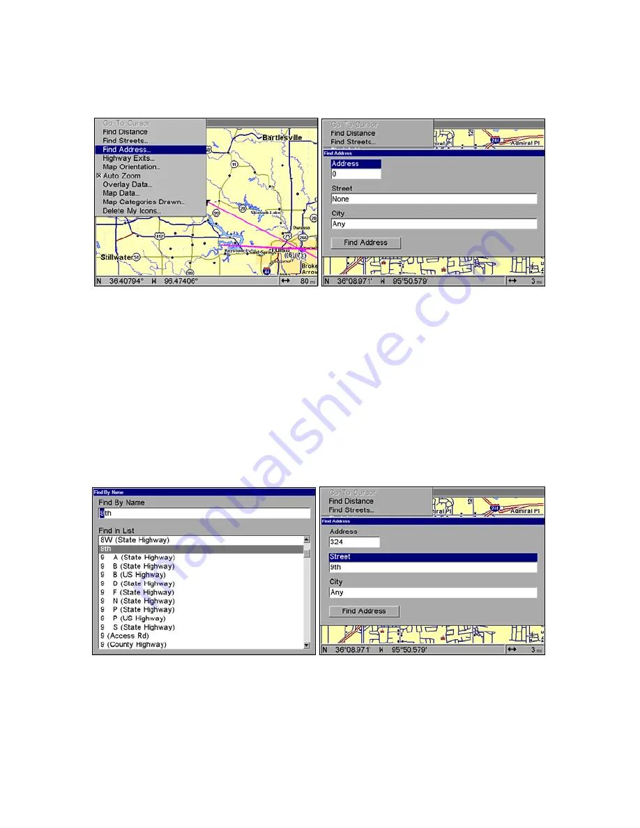
Find Addresses 

1. From the Map Page, press 

MENU

|

 to 

F

IND 

A

DDRESS

|

ENT.


2. Press 

ENT

 to search in the Address field. 


Find Address Menu. 

3. 

To enter an address

press 

 or 

 to change the first number, then


press 

 to move the cursor to the next number and repeat until the 

number


is correct, then press


ENT

.


4. 

To enter a street name

press 

 to 

STREET

|

ENT. 

There are two options: 

A.

 You can spell out the name in the top selection box. Press 

 or 

 to 

change the first letter, then press 

 to move the cursor to the next 

letter and repeat until the name is correct, then press 

ENT

|

ENT. 

B.

 Or 

jump down to the lower selection list by pressing 

ENT

, then press 

 or 


to select a street name from the list and press 

ENT.

 The street name you 

selected is now in the street field. 


Find Street menu (left) with Find By Name field active; street name 

entry complete (right). 

5. 

To enter a city name

press


to 

C

ITY

|

ENT

You will be asked if you want 

to find addresses only within a particular city. This option is designed 
to limit an address search to a single city, if necessary. 

Summary of Contents for LCX-112C

Page 1: ...Pub 988 0151 511 www lowrance com LCX 27C LCX 28C HD LCX 37C LCX 38C HD LCX 112C LCX 113C HD Fish finding Sonar Mapping GPS Operation Instructions ...

Page 2: ...d trademark of the National Marine Electronics Association Points of Interest Data in this unit are by infoUSA copyright 2001 2006 All Rights Reserved infoUSA is a trademark of infoUSA Inc Additional mapping data copyright 2006 by Transas Ltd copyright 2006 by Maptech Inc Lowrance Electronics may find it necessary to change or end our policies regulations and special offers at any time We reserve ...

Page 3: ...Trolling Motor Bracket Installation single frequency only 19 Transducer Orientation and Fish Arches 20 Shoot thru hull Preparation 21 Shoot thru hull Installation 23 Speed Temperature Sensors 25 GPS Antenna Receiver Module 26 Power Connections 27 Powering Your Display Unit 28 Power Diagram A 29 Power Diagram B 30 Powering a NMEA 2000 Network Bus 30 NMEA 2000 Cable Connections 31 NMEA 0183 Wiring D...

Page 4: ...d 64 Chart Speed 65 Colorline 65 Customize Page Displays 68 FlashGraf 69 Map With Sonar Split Screen 69 Sonar with Custom Gauges 70 Depth Cursor 70 Depth Range Automatic 71 Depth Range Manual 71 Depth Range Upper and Lower Limits 72 FasTrack 73 Fish I D Fish Symbols Depths 74 FishTrack 75 Frequency Change Transducer Frequency 76 Log Sonar Chart Data 77 Overlay Data add remove change 78 Ping Speed ...

Page 5: ...round the Map Zoom Cursor Arrow Keys 112 Selecting Any Map Item with the Cursor 113 Searching 113 Set a Waypoint 115 Create Waypoint at Current Position 115 Create Waypoint on Map 116 Create Waypoint by Entering a Position 117 Navigate To a Waypoint 117 Set Man Overboard MOB Waypoint 118 Navigate Back to MOB Waypoint 118 Navigate to Cursor Position on Map 119 Navigate to a Point of Interest 120 Cr...

Page 6: ... Pattern 137 Utilities 138 Alarm Clock 138 Sun Moon Rise Set Calculator 138 Trip Calculator 138 Trip Down Timer 138 Trip Up Timer 138 Waypoints 138 Delete a Waypoint 138 Edit a Waypoint name symbol position 138 Selecting a Waypoint 139 Set a Waypoint by Average Position 139 Set a Waypoint by Projecting a Position 139 Section 8 System GPS Setup Options 141 Alarms 141 Auto Satellite Search 142 Check...

Page 7: ... 159 To display a Navionics chart 160 Overlay Data add remove change 160 Popup Help 166 Reset Options 166 Screen Contrast and Brightness 167 Set Language 168 Set Local Time 168 Show WAAS Alarm 169 Software Version Information 170 Sounds and Alarm Sound Styles 170 Track Smoothing 171 Trail Options 171 Delete All Trails 172 Update Trail Options 172 Delete Trail 173 New Trail 173 Trail Visible Invisi...

Page 8: ...ronization 194 Configuring EP Sensors 194 EP 35 Temperature Configuration 194 Advanced Options menu 195 EP 10 Fuel Flow Configuration 196 Advanced Options menu 197 EP 15 Fluid Level Configuration 198 Advanced Options menu 199 Suzuki Engine Interface Configuration 200 Advanced Options menu 201 Calibrating EP Sensors 202 EP 10 Fuel Flow Calibration 202 EP 15 Fluid Level Calibration 204 Fuel Flow Cal...

Page 9: ...ling to a waypoint but will also visually check to make sure a clear safe path to the waypoint is always available WARNING When a GPS unit is used in a vehicle the vehicle operator is solely responsible for operating the vehicle in a safe manner Vehicle operators must maintain full surveillance of all pertinent driving boating or flying conditions at all times An accident or collision resulting in...

Page 10: ...viii Notes ...

Page 11: ...ime reading the manual So we designed our book so you don t have to read the whole thing from front to back to find the information you want At the start or end of each segment we ll tell you what content is coming up next If it s a concept you re already familiar with we ll show you how and where to skip ahead for the next important topic We ve also made it easy to look up any tips you may need f...

Page 12: ...you can look it up in the manual by skimming over the table of contents flipping through Section 6 or scanning through the command portion of Section 7 This unit is ready to use right out of the box but you can fine tune and customize its operation with dozens of options Since sonar is the unit s key feature we put the main sonar options in Section 4 Some options such as screen brightness settings...

Page 13: ...he transmitter emits an electrical impulse which the transducer converts into a sound wave and sends into the water Humans or fish can t hear the sound frequency The sound wave strikes an object fish structure or bottom and bounces back to the transducer which converts the sound back into an electrical signal The receiver amplifies this return signal or echo and sends it to the display where an im...

Page 14: ...s as it can see above the horizon eliminates the weakest signals then computes its location in relation to those satellites Once it figures its latitude and longitude the unit plots that position on the moving map shown on the screen The whole process takes place several times a second The performance doesn t stop there Stored in the permanent memory of every unit is a basic background map of the ...

Page 15: ...e these GPS Data Files on a personal computer equipped with an MMC card reader Or store them on a pocketful of MMCs if you don t have a computer Our MapCreate mapping software can save edit or create its own GPS Data Files which can be copied to the MMC and then loaded from the MMC into the unit s memory The other key GPS use for MMCs is storage of special high detail custom maps which you can pro...

Page 16: ...atellites orbit 10 900 nautical miles above the Earth passing overhead twice daily A series of ground stations with precisely surveyed locations controls the satellites and monitors their exact locations in the sky Each satellite broadcasts a low power signal that identifies the satellite and its position above the earth Three of these satellites are spares unused until needed The rest virtually g...

Page 17: ...ore accurate Your unit receives both GPS and WAAS signals WAAS however has some limits you should know about WAAS can boost the accuracy of land GPS navigation but the system is designed for aircraft The satellites are in a fixed orbit around the Equator so they appear very low in the sky to someone on the ground in North America Aircraft and vessels on open water can get consistently good WAAS re...

Page 18: ... you need to select are show in italic type such as trail name Instructions Menu Sequences Most functions you perform with this unit are described as a sequence of key strokes and selecting menu commands We ve written them in a condensed manner for quick and easy reading For example instructions for navigating a trail would look like this 1 From the Map Page press MENU MENU to MY TRAILS ENT 2 Pres...

Page 19: ...ransducer and route the transducer cable to the sonar GPS unit 6 Install the GPS antenna and route the antenna cable to the sonar GPS unit 7 Install the power cable and route it to the sonar GPS unit 8 Mount the sonar GPS unit Transducer Installation These instructions will help you install your Skimmer transducer on a transom on a trolling motor or inside a hull These instructions cover both sing...

Page 20: ...ble wrenches drill 20 0 161 drill bit flat head screwdriver Supplies four 1 long 12 stainless steel slotted wood screws high quality marine grade above or below waterline sealant adhesive compound Single frequency trolling motor installations Tools two adjustable wrenches flat head screwdriver Supplies plastic cable ties Shoot through hull installations Tools these will vary depending on your hull...

Page 21: ...re but the principle is the same for Skimmers inside a hull 4 If the transducer is mounted on the transom make sure it doesn t interfere with the trailer or hauling of the boat Also don t mount it closer than approximately one foot from the engine s lower unit This will prevent cavitation bubble interference with propeller operation 5 If possible route the transducer cable away from other wiring o...

Page 22: ...higher for more protection There are two extremes you should avoid Never let the edge of the mounting bracket extend below the bottom of the hull Never let the bottom the face of the transducer rise above the bottom of the hull Shoot thru hull vs Transom Mounting In a shoot thru hull installation the transducer is bonded to the inside of the hull with epoxy The sonar ping signal actually passes th...

Page 23: ...n at the end of this lesson to determine if you can satisfactorily shoot through the hull Transom Transducer Assembly and Mounting The best way to install these transducers is to loosely assemble all of the parts first place the transducer s bracket against the transom and see if you can move the transducer so that it s parallel with the ground The following instructions sometimes vary depending o...

Page 24: ...ters molded into each ratchet Place the ratchets into the bracket with the letter A aligned with the alignment mark molded into the bracket Place the ratchets onto the transducer with the letter A aligned with the 12 o clock position on the transducer stem These positions set the transducer s coarse angle adjustment for a 14 transom Most outboard and stern drive transoms have a 14 angle Insert and...

Page 25: ...cer s face isn t parallel with the ground remove the transducer and ratchets from the bracket Place the ratchets into the holes in the bracket with the letter B aligned with the dot stamped in the bracket Reassemble the transducer and bracket and place them against the transom Again check to see if you can move the transducer so it s parallel with the ground If you can then go to step 3A If it doe...

Page 26: ...ed with the bracket alignment mark Place them on the transducer aligned with the 12 o clock position on the transducer stem Reassemble the transducer and bracket and place them against the transom Again check to see if you can move the transducer so it s parallel with the ground If you can then go to step 3B If it doesn t repeat step 2B but use a different alignment letter until you can place the ...

Page 27: ...ot for the mounting screw pilot holes You will drill one hole in the center of each slot Drill the holes For the one piece bracket use the 29 bit for the 10 screws For the two piece bracket use the 20 bit for the 12 screws Position transducer mount on transom and mark mounting holes Side view shown left and seen from above right 5 Attaching transducer to transom A One piece bracket Remove the tran...

Page 28: ...ansom to the sonar unit Make sure to leave some slack in the cable at the transducer If possible route the transducer cable away from other wiring on the boat Electrical noise from the engine s wiring bilge pumps VHF radio wires and cables and the sonar can pick up aerators Use caution when routing the transducer cable around these wires WARNING Clamp the transducer cable to the transom close to t...

Page 29: ...e internal tooth washer is supplied with the TMB S Attach motor mounting bracket to transducer 2 Slide the adjustable strap supplied with the TMB S through the slot in the transducer bracket and wrap it around the trolling motor Position the transducer to aim straight down when the motor is in the water Tighten the strap securely 3 Route the transducer cable alongside the trolling motor shaft Use ...

Page 30: ...ut not back down then the front of the transducer is too high and needs to be lowered If only the back half of the arch is printed then the nose of the transducer is angled too far down and needs to be raised NOTE Periodically wash the transducer s face with soap and water to remove any oil film Oil and dirt on the face will reduce the sensitivity or may even prevent operation Transducer aimed too...

Page 31: ...erglass The transducer can then be epoxied directly to the outer layer of fiberglass After the epoxy cures for 24 hours fill the remaining space with polyester resin When the job is finished the hull is watertight and structurally sound Remember the sonar signal must pass through solid fiberglass Any air bubbles in the fiberglass or the epoxy will reduce or eliminate the sonar signals WARNING Do n...

Page 32: ...Depth Range and ASP Try a range setting that is two to three times the water depth The harder more rocky the bottom the easier it will be to get a second bottom signal Don t touch the controls once they ve been set Example of a second bottom signal Unit is in 30 feet of water with range set at 80 feet and sensitivity set at 87 percent 2 Next take the transducer out of the water and place it in the...

Page 33: ...at your selected location will work under all conditions make a test run with the boat on plane and observe the bottom signal You ll need to figure some way to prop the transducer into position while you make your test run A brick or two might be sufficient to hold it in place 5 When you re satisfied with a location mark it and proceed with the installation Shoot thru hull Installation If you are ...

Page 34: ...s shown in the previous figure Make sure there are no air pockets in the epoxy layer Then apply the remaining epoxy to the sanded area on the hull 3 Press the transducer into the epoxy twisting and turning it to force any air bubbles out from under the transducer face Stop pressing when you bottom out on the hull When you re finished the face of the transducer should be parallel with the hull with...

Page 35: ... or ribs These will disturb the water flow to the speed sensor Make sure the sensor will remain in the water when the boat is on plane Also make sure the location doesn t interfere with the boat s trailer Typically the sensor is mounted about one foot to the side of the transom s centerline Once you ve determined the proper location for the unit place the sensor on the transom The bottom of the br...

Page 36: ...alant used for the screws The sensor is now ready for use Connect the sensor to the sonar socket on the back of your unit and connect the transducer to the speed sensor s socket If you have any questions concerning the installation of the sensor please contact your local boat dealer GPS Antenna Receiver Module The LCX 27C LCX 28C HD LCX 37C LCX 38 C HD LCX 112C and LCX 113C HD packages include the...

Page 37: ... truck camper or motor home If dashboard reception is poor simply relocate the antenna module elsewhere on the vehicle for a clearer view of the sky Power Connections Your unit comes with a power data cable that splits into three branches each with several exposed wires The thicker two wire cable red and black is the power supply for your display unit This cable has no label The branch with three ...

Page 38: ...e strongly recommend that you shut off the power supply to the power cable when the unit is not in use especially in saltwater environments When the unit is turned off but still connected to a power supply electrolysis can occur in the power cable plug This may result in corrosion of the plug body along with the electrical contacts in the cable and the unit s power socket Risk of electrolysis corr...

Page 39: ...ure to attach the in line fuse holder to the red lead as close to the power source as possible For example if you have to extend the power cable to the power bus or battery attach one end of the fuse holder directly to the power bus or battery This will protect both the unit and the power cable in the event of a short This unit has reverse polarity protection No damage will occur if the power wire...

Page 40: ...ding a GPS module The method in diagram B is also used when your display unit is connected to a NMEA 2000 network that is already connected to power Never connect multiple power sources to a NMEA 2000 network Powering a NMEA 2000 Network Bus A NMEA 2000 bus must be connected to a power source to operate NMEA 2000 devices including GPS modules draw their power from the network bus If you have a pre...

Page 41: ...try standard and at the time of printing some boats being built now have a NMEA 2000 bus installed Over the next few years however NMEA 2000 will become much more common To help you get the most out of this technology your Lowrance unit is designed to work with a NMEA 2000 network Connecting to a NMEA 2000 Network A network bus is an installed and operational network cable backbone running the len...

Page 42: ...e NMEA 0183 data this unit has two NMEA 0183 version 2 0 communication ports Serial Communications Port one Com1 and Serial Communications Port two Com2 can be used to transmit or receive NMEA format GPS data The five wires for the Serial Communications Ports are combined with the Display Unit Power cable and NMEA 2000 Power cable to form the power data cable shown earlier Com1 uses the yellow wir...

Page 43: ...another device Com 2 wiring to exchange position information Orange Receive Shield Ground Transmit Ground Com 1 To unit To Other Device Yellow Transmit Receive Green Receive Shield Ground Transmit Ground Com 2 To unit To Other Device Blue Transmit Receive ...

Page 44: ...iew GPS antenna module Power Data socket Extension cables NMEA 2000 power cable Sonar socket Transducer Network socket Optional speed sensor 120 ohm terminator NMEA 0183 data cable Ethernet socket for future use Display unit power cable Double T connector terminator ...

Page 45: ... Display unit rear view Sonar socket Power Data socket Network socket Optional speed sensor Transducer GPS antenna module Extension cables 120 ohm terminator NMEA 2000 Power Cable terminator Double T connector Display unit power cable Ethernet socket for future use ...

Page 46: ...splay unit rear view Sonar socket Network socket Optional speed sensor Extension cables 120 ohm terminator GPS antenna module Transducer NMEA 2000 Power Cable NMEA 0183 Data Cable Ethernet socket for future use terminator Double T connector Display unit power cable ...

Page 47: ...he backbone are similar to telephone jacks spread throughout a house To pick up a phone and be able to hear a conversation from another phone in the house both phones must be connected to the main phone line In similar fashion only sensors and display units plugged into the NMEA network can share information The network backbone is like the phone wiring that runs throughout a home It connects the ...

Page 48: ...s of the existing connection and install the T connector between them Add a new device to a NMEA 2000 bus by attaching a T connector between two T connectors between a T connector and the end terminator or between two backbone extension cables If you want to add a node at the end of the backbone network bus remove the terminator from the last connector like the figure above Install the new T conne...

Page 49: ... dash with the gimbal bracket It can also be installed in the dash or mounted on a portable power supply If you use the supplied bracket you may be interested in the optional R A M bracket mounting system This converts the unit s gimbal bracket to a swivel mount which can be used on the dash or overhead mounting positions Optional R A M mounting system Bracket Installation Mount the unit in any co...

Page 50: ... piece of plywood on the backside of thin fiberglass panels to reinforce the panel and secure the mounting hardware Install the gimbal bracket Place the bracket so the arms slope toward the front of your unit Once a location is determined use the bracket as a template and mark the mounting holes and the hole for the cables Drill a 1 inch 25 4 mm hole in the dash for the power transducer and antenn...

Page 51: ...d side view right showing dimensions of the LCX 27C and LCX 28C HD mounted on gimbal brackets Front view left and side view right showing dimensions of the LCX 112C and LCX 113C HD mounted on gimbal brackets Millimeter Inch ...

Page 52: ...le from the top If you wish you can fill in the hole around the cables with a good marine caulking compound No matter what type of installation you prefer be sure to leave enough slack in the cables to allow tilting or swiveling the unit Attach the unit to the gimbal bracket using the supplied gimbal knobs and washers Attach the cables and the unit is ready to use In Dash Installation You can moun...

Page 53: ...used at the same time Throughout this manual we will use the term MMC but just remember your unit can use an MMC or SD card to store data NOTE The LCX 28CHD and LCX 113CHD have NauticPath charts Hot Spots Elite charts and all high detail custom maps preloaded onto a 30 Gigabyte hard drive Therefore if you own either the LCX 28CHD or the LCX 113CHD you do not need to load any of those charts maps i...

Page 54: ...drawer is located on the front of the LCX 27C and LCX 28C HD units To install an MMC twist the drawer retainer counter clockwise and pull The drawer will come out of the units Place the MMC in the drawer face down see following figures Memory card drawer on the LCX 27C and LCX 28CHD Slide the drawer back into the unit and twist the retainer clockwise The MMC is now ready for use In the LCX 37C LCX...

Page 55: ...cation To add an MMC or SD Card 1 Open the card compartment door 2 Grasp the bottom of the MMC and push the top of the card into the slot Once the card is started press down in the center of the card with the ball of your finger or thumb and push the card all the way to the left until it is firmly seated in the slot 3 Close the compartment door and fasten the thumbscrew finger tight Other Accessor...

Page 56: ...operation NOTE When you first turn the unit on the Map Page appears If you d rather start learning about GPS operation first turn to Sec 6 Basic GPS Operations Remember you don t need to read this manual from cover to cover to get going We designed it so you can skip around to the section you want to read Cleaning Towel A lint free microfiber towel is included for cleaning the unit s screen The to...

Page 57: ...earn about the different keys the Main Menu the four Page screens and how they all work together BUT if you just can t wait to get on the water turn to the one page Quick Reference on page 55 Keyboard LCX 28CHD sonar GPS unit front view showing sonar screen keyboard and access door for the MMC compartment 1 PWR LIGHT Power Light The PWR key turns the unit on and off and activates the backlight 2 P...

Page 58: ...his key lets you zoom the screen out On the Sonar Page this key returns you to a full sonar chart display showing the entire water column from surface to bottom On the Map Page this lets you see a larger geographic area on the map Less detail is seen as you zoom out 9 ZIN Zoom In This key lets you zoom the screen in On the Sonar Page this key enlarges fish signals and bottom detail On the Map Page...

Page 59: ...equences Main Menu The Main Menu commands and their functions are Screen command changes the contrast or brightness of the display Sounds command enables or disables the sounds for key strokes and alarms and sets the alarm style Transparency command allows you to change the thickness of the dialog boxes so you can see through the dialog box Alarms command turns GPS alarms on or off and changes ala...

Page 60: ...e unit has five Page displays that represent the five major operating modes They are the Satellite Status Page the Navigation Page the Map Page Sonar Page and Radar Page For more information about the Radar see the Radar Manual You can access these pages by pressing the PAGES key then using or to select a Page Pres EXIT to clear the Pages Menu Pages Menu showing sonar display options Satellite Sta...

Page 61: ... navigating with this unit until the numbers have stopped flashing Satellite Status Page Navigation Page This screen has a compass rose that not only shows your direction of travel but also the direction to a recalled waypoint To get to the Navigation Page press PAGES or to NAVIGATION EXIT This page represents the GPS function so it is discussed in more detail in Sec 6 The Navigation Page left nav...

Page 62: ...is discussed in Sec 4 Sonar Options Other Features The Map Page represents a GPS function so it is discussed in more detail in Sec 6 Sonar Page The Sonar Page displays the sonar chart This is a cross section view of the water column beneath the boat The chart moves across the screen displaying sonar signal echoes that represent fish structure and the bottom To get to the Sonar Page press the PAGES...

Page 63: ...ar chart display option commands left Sonar display options full sonar chart left and split zoom chart right Sonar chart display options from left digital data and FlashGraf Sonar chart display options Sonar with Custom Gauges ...

Page 64: ...all of those features and options in Sec 4 but to show you how easy the unit is to operate the following page contains a simplified 10 step quick reference that will cover most fish finding situations The quick reference describes how your unit will operate with all the sonar features in their automatic modes which are set at the factory Surface clutter Structure Bottom signal Fish arches In FasTr...

Page 65: ...of the screen The full sonar chart will scroll from right to left showing you what s under the boat as you cruise across the water You can change the display by Zooming in to enlarge the chart for more detail press ZIN Zooming out to return to full chart mode press ZOUT 7 Watch the display for the appearance of fish arches When you see arches you ve found fish Stop the boat and get your lure or ba...

Page 66: ...If you want to see more detail try increasing the sensitivity a little at a time There are situations when too much clutter appears on the screen Decreasing the sensitivity can reduce the clutter and show the strongest fish echoes if fish are present As you change the sensitivity setting you can see the difference on the chart as it scrolls These figures show results of different sensitivity level...

Page 67: ... auto turned on the unit will continue to track the bottom and make minor adjustments to the sensitivity level with a bias toward the setting you selected Adjusting sensitivity in Manual Sensitivity Mode is similar to driving a car without cruise control you have complete control of the car s speed In this unit manual mode allows you to set sensitivity at 100 percent maximum or zero percent minimu...

Page 68: ...rt mode for our example and not the popular Fish I D fish symbol feature Here s why Fish I D is an easier way for a sonar novice to recognize a fish signal return when he sees it However locating a fish via symbol has some limitations Your sonar unit s microprocessor is remarkably powerful but it can be fooled Some of the echoes calculated to be fish could be tree limbs or turtles To see what s un...

Page 69: ...itivity Colorline noise rejection surface clarity etc of the recorded file Interpretation of sonar signals can be user defined Operates like a Windows Multimedia Player with forward reverse pause fast forward fast reverse and scroll buttons Adjustments update the entire record displayed Window can dynamically be sized on your monitor Mouse cursor shows GPS position depth and sounding number anywhe...

Page 70: ...xactly like your real sonar GPS unit Using the Sonar Simulator and GPS Simulator features it allows you to play back sonar logs run GPS routes and trails even create real waypoints you can use in the field You can even take snapshots of the Sonar Chart and print them or e mail them to friends ...

Page 71: ... In all cases noise can produce unwanted marks on the display The ASP feature has four settings Off Low Medium and High If you have high noise levels try using the High ASP setting However if you are having trouble with noise we suggest that you take steps to find the interference source and fix it rather than continually using the unit with the high ASP setting There are times when you may want t...

Page 72: ...tting For example if you set the shallow alarm to 10 feet the alarm will sound a tone if the bottom signal is less than 10 feet It will continue to sound until the bottom goes deeper than 10 feet The deep alarm works just the opposite It sounds a warning tone if the bottom depth goes deeper than the alarm s setting Both depth alarms work only off the digital bottom depth signals No other targets w...

Page 73: ...alarm bar shown on the right side of the screen To adjust and turn on the zone alarm 1 Press MENU MENU to ALARMS ENT to SONAR ALARMS ENT 2 Press to ZONE ALARM ENABLED to ADJUST ZONE ENT Sonar Alarms menu with Adjust Zone command selected left Adjust Zone Alarm selection box with Upper Limit selected right 3 To set the upper boundary for the Zone Alarm use or to select UPPER then press or to move t...

Page 74: ...ensor s performance is to compare its reading with the ground speed measured by your unit s GPS functions When you make a run to compare the GPS ground speed to the speed sensor perform your test in relatively current free calm water if possible Unless of course you are taking the current speed into consideration when making your calculation For example if you figure the sensor is reading 1 percen...

Page 75: ...y result in a shorter line that more closely resembles a regular fish return Sonar Page menu with Chart Speed command selected left The Chart Speed Control Bar right If you do experiment with chart speed remember to reset it to maximum when you resume trolling or moving across the water at higher speed To change chart speed 1 From the Sonar Page press MENU to CHART SPEED ENT 2 The Chart Speed Cont...

Page 76: ...s the stronger signal This helps distinguish weeds from trees on the bottom or fish from structure Colorline is adjustable Experiment with your unit to find the Colorline setting that s best for you Sonar Page menu with Colorline command selected left The Colorline control bar right To adjust the Colorline level 1 From the Sonar Page press MENU to COLORLINE ENT 2 The Colorline Control Bar appears ...

Page 77: ...w the same locations with Colorline increased to 84 percent In Figure 1B no fish are near the left structure but the right structure shows fish holding next to the structure Colorline Muddy bottom Hard bottom Muddy bottom Fish near structure Hard bottom Hard structure Colorline Colorline Fig 2A Fig 3A Fig 2B Fig 3B Fig 1A Fig 1B ...

Page 78: ... the box or hit or to select another box then press ENT You ll see a list of categories with or symbols next to each category A category with a is expandable meaning its contents are hidden Data Viewer with the Sonar Data category expanded Selecting the category name and pressing ENT will show the category s contents so you can choose items within it An expanded category one with a next to its nam...

Page 79: ... shown as a black bar across the outer circle You can adjust the size of the chart and the flasher windows by using the Resize Window command found on page 109 FlashGraf page Map With Sonar Split Screen There is a page mode that splits the screen in half with the map on the left and the sonar on the right This screen option can be found on the Pages Menu under the Map Page category Map with Sonar ...

Page 80: ... Data dialog box will appear Press ENT to add data A data viewer box will appear Press ENT to modify the box or hit or to select another box then press ENT You ll see a list of categories with or symbols next to each category A category with a is expandable meaning its contents are hidden Sonar with Custom Gauges Depth Cursor The depth cursor consists of a horizontal line with a digital depth box ...

Page 81: ...epth Range Control Scale right 2 The Depth Range Control Scale appears Press or to select a different depth range A blue bar highlights the selected range The shaded numbers cannot be selected 3 When the new range is selected press EXIT to clear the menu Depth Range Manual You have complete control over the range when the unit is in the manual mode There are 16 depth ranges from 5 to 4 000 feet To...

Page 82: ... to the bottom can be shown This enlarges the sonar targets to best suit your fishing needs and water conditions Sonar Page Menu with Upper and Lower Limits command selected left Sonar Chart Limits menu with Upper Limit selected right To change the upper and lower limits 1 From the Sonar Page press MENU to UPPER AND LOWER LIMITS ENT The Sonar Chart Limits menu appears with Upper Limit selected 2 T...

Page 83: ...ort horizontal lines on the display s far right side The rest of the screen continues to operate normally FasTrack gives you a rapid update of conditions directly under the boat This makes it useful for ice fishing or fishing at anchor When the boat is not moving fish signals are long drawn out lines on a normal chart display FasTrack converts the graph to a vertical bar graph that with practice m...

Page 84: ...les etc Individual tree limbs extending outward from a group of limbs are the hardest objects for the Fish I D feature to distinguish from fish You may see fish symbols on the screen when there actually are no fish The reverse also is true Does that mean Fish I D is broken No The feature is interpreting sonar returns in a specific way to help take some of the work out of reading the screen Remembe...

Page 85: ...only when the Fish I D feature is on The default setting for FishTrack is off To turn on FishTrack Note These instructions will turn on FishTrack and Fish I D at the same time 1 From the Sonar Page press MENU to SONAR FEATURES ENT 2 Press to FISH DEPTHS ENT EXIT EXIT To turn off FishTrack repeat the instructions in step 1 Turning off FishTrack in this manner will not turn off Fish I D symbols Fish...

Page 86: ...f the fresh and saltwater sport fishing applications When you get into very deep saltwater 300 to 500 feet or deeper the 50 kHz frequency is the best choice The 200 kHz transducer will give you better detail and definition but less depth penetration The 50 kHz transducer will give you greater depth penetration but a little less detail and less definition Remember all sonar units typically read dee...

Page 87: ...S ENT 2 Press to 200 KHZ ENT 3 Press EXIT EXIT to clear the menu Log Sonar Chart Data If you have an MMC installed in the unit the sonar data shown on the screen can be saved to it This can be played back at any time To play a recorded sonar chart log see the entry in this section for Sonar Simulator If you have a personal computer and internet access download our free Sonar Viewer and your unit s...

Page 88: ...using the cursor arrows to highlight different commands Select FILE NAME if you want to change the name Select CHART QUALITY if you want to lower the file quality and record for a longer period After you ve changed the settings select START LOGGING Overlay Data On any page display except the Satellite Status and Navigation pages you can float or overlay additional data on the screen with the Overl...

Page 89: ... press ENT 3 Expand any categories that might contain data you want to display Then press or to select a data option 4 With the data option highlighted press ENT to check it turn it on or uncheck it turn it off As you turn it on the data will appear on top of the screen Every Page display has a maximum number of items you can show using the Overlay Data command 5 After the desired changes are made...

Page 90: ...When satisfied press EXIT EXIT NOTE The Customize command and the Overlay Data command use the same information categories The difference between the two commands is the Customize command is only used to modify pages with digital data boxes while Overlay Data changes information floating on the screen See Customize Page Displays on page 68 for information on customizing data boxes To change displa...

Page 91: ...r data to suit your viewing preferences To access overlaid data style menu 1 Press MENU to OVERLAY DATA ENT 2 This will bring up the Overlay Data Shown menu with a list of current overlay data Highlight the data you want to change on the Overlay Data Shown menu and press ENT which will launch the data information menu 3 Use to select overlay style choose analog and press ENT 4 Next press to enter ...

Page 92: ...l boating speeds this automatically provides enough return echoes to refresh the screen and scroll the chart at maximum chart speed However when you are running at high speeds or just want the fastest possible screen update you may want to use the HyperScroll feature When you change the Ping Speed to any setting greater than 50 percent the unit automatically enters HyperScroll mode These faster pi...

Page 93: ...eed to 50 percent When it s set at the desired level press EXIT When you boost ping speed and switch into HyperScroll the width of the FasTrack bar graph display doubles at the right side of the screen This allows you to see the virtually instantaneous sonar returns better just as you would on a flasher sonar unit For more information on FasTrack see its entry in this section Reset Options This co...

Page 94: ...chart depth scale chart cursor or fish symbols is not exact If the transducer is 1 foot below the surface and the screen shows the water depth as 30 feet then the actual depth is 31 feet On sailboats or other large vessels with deep drafts the distance between the transducer installation and the keel or lower engine unit can be several feet In those cases an inexact depth reading could result in g...

Page 95: ... 2 Use to scroll down to KEEL OFFSET then press ENT The Keel Offset dialog box appears with a plus sign at the front of the box 3 Press to the first number then press to change the number to 1 4 Press to the second number then press to change the number to 5 and press EXIT The depth indicator now accurately shows the water depth from surface to bottom Sensitivity Auto Sensitivity Sensitivity contr...

Page 96: ...In manual mode you have complete control over sensitivity with the ability to set it anywhere from zero to 100 percent Once you select a level in manual the unit will continue to use that exact sensitivity setting until you change it or revert to auto mode To adjust sensitivity in auto mode 1 Press MENU ENT 2 The Sensitivity Control Bar appears Press to decrease sensitivity press to increase sensi...

Page 97: ... are matching the sensitivity to rapidly changing water conditions Sonar Chart Mode The default color scheme for the sonar chart is white background but we offer other variations to suit your viewing preferences The chart can be displayed in Grayscale Reverse Grayscale Blue Background White Background Nightview IceView or Bottom Color Tracking To change the chart mode 1 From the Sonar Page press M...

Page 98: ...display shows just to the right of the scale This changes all echoes into short horizontal bars replicating the flasher sonar The zoom bar on the far right shows the area magnified when the zoom is in use See the Zoom section on page 92 for more information Full Sonar Chart The Overlay Data depth and water temperature are each set to a different text size Split Zoom Sonar Chart A split chart shows...

Page 99: ... you will see the chart file name in the Sonar Page title bar and a play symbol will flash on and off at the right end of the title bar To use the simulator 1 From the Sonar Page press MENU MENU to SYSTEM SETUP ENT to SIMULATORS ENT 2 A tabbed menu will appear on screen Press to SONAR SIMULATOR SONAR SIMULATOR ON ENT Main Menu with System Setup command selected left Sonar Simulator menu with simul...

Page 100: ...ress to CHART USED ENT 3 Use or to select chart name ENT to SONAR SIMULATOR ON ENT EXIT While you re in the Sonar Simulator menu don t forget to check Simulate Position if you want to run the sonar and GPS simulators simultaneously As you review sonar logs you can create waypoints to mark sites you want revisit While the simulator is running you can switch from one chart log to another by opening ...

Page 101: ... Surface Clarity The markings extending downward from the zero line on the chart are called surface clutter Wave action boat wakes temperature inversion and more cause these markings The surface clarity control reduces or eliminates surface clutter signals from the display It does this by changing the sensitivity of the receiver decreasing it near the surface and gradually increasing it as the dep...

Page 102: ...entry in this section for Depth Range Upper and Lower Limits User Presets The unit has two user presets that you can set This is useful if you have two people with different preferences using the unit To access the User Presets from the Sonar Page MENU to SONAR FEATURES SONAR PRESETS ENT To name the presets 1 MENU to SONAR FEATURES ENT PRESET NAME ENT 2 Use or to change the first character 3 Use t...

Page 103: ... 2X zoom that will show all echoes that are between the top and bottom of the 2X zoom bar Pressing the key again will give a 4X zoom and only the echoes between the top and bottom of the 4X bar will show on the screen Press the Zoom Out key ZOUT to return the display to the normal mode Sonar page zoomed 2X left The same view zoomed 4X right Zoom Pan Your unit has the handy ability to quickly zoom ...

Page 104: ...94 Notes ...

Page 105: ...have been disconnected To leave demo mode make sure that either the transducer or the antenna is securely connected before turning the unit on Unit freezes locks up or operates erratically 1 Electrical noise from the boat s motor trolling motor or an accessory may be interfering with the sonar unit Rerouting the power and transducer cables away from other electrical wiring on the boat may help Rou...

Page 106: ... to find the bottom or other targets The technical term for this is cavitation 2 Electrical noise from the boat s motor can interfere with the sonar This causes the sonar to automatically increase its Discrimination or noise rejection feature This can cause the unit to eliminate weaker signals such as fish or even structure from the display Try using resistor spark plugs or routing the sonar unit ...

Page 107: ...ransducer cable away from the wiring that is causing the interference VHF radio antenna cables radiate noise when transmitting so be certain to keep the sonar s wires away from it You may need to route the sonar unit s power cable directly to the battery to isolate it from other wiring on the boat If no noise displays on the sonar unit from electrical equipment then make certain everything except ...

Page 108: ...98 Notes ...

Page 109: ... four Page screens and how they all work together BUT if you just can t wait to get outside turn to the one page Quick Reference on page 111 Keyboard LCX 113CHD sonar GPS unit front view showing sonar screen keyboard and access doors for the MMC compartments 1 PWR LIGHT Power Light The PWR key turns the unit on and off and activates the backlight 2 PAGES Pressing this and the arrow keys 4 switches...

Page 110: ...n the map You see less detail zooming out 9 ZIN Zoom In This key lets you zoom in on the map On the Sonar Page this key enlarges fish signals and bottom detail On the Map Page zooming in lets you see more detail in a smaller geographic area on the map Power lights on and off To turn on the unit press PWR As the unit powers up the Map Page is displayed first To switch to another page press PAGES or...

Page 111: ...ils Also used to navigate or backtrack a trail Cancel Navigation command turns off the various navigation commands Used to stop navigating after you have reached your destination waypoint Point of Interest or map cursor location or after you reach the end of a route or trail Sonar Setup command sets various sonar options GPS Setup command sets various GPS receiver options System Setup command sets...

Page 112: ...ail in Sec 3 To get to the Sonar Page Press the PAGES key then use or to select SONAR Clear the Pages Menu by pressing EXIT Satellite Status Page The Satellite Status Page provides detailed information on the status of the unit s satellite lock on and position acquisition To get to the Satellite Status Page Press the PAGES key then use or to select STATUS Clear the Pages Menu by pressing EXIT No m...

Page 113: ...ellite in view Since the unit has twelve channels it can dedicate one channel per visible satellite The taller the bar on the graph the better the unit is receiving the signals from the satellite The Estimated Position Error horizontal position error shown in the upper left corner of the screen is the expected error from a benchmark location In other words if the EPE shows 50 feet then the positio...

Page 114: ...ng toward the waypoint For instructions see the Customize Page Displays entry in Sec 8 Track is the heading or the current direction you are actually traveling Bearing is the direction of a line of sight from your present position to the destination No matter what direction you are steering the Bearing window shows the compass direction straight to the destination from your location at the moment ...

Page 115: ... options Options and setup are discussed in Sec 8 To access the Navigation Page Menu from the Navigation Page press MENU Map Page The Map Page screens show your course and track from a bird s eye view By default this unit shows the map with north always at the top of the screen This can be changed See the topic Map Orientation in Sec 8 If you re navigating to a waypoint the map also shows your sta...

Page 116: ...il MapCreate map Arterial streets appear at the 6 mile zoom range with a few Point of Interest icons visible left Numerous Points of Interest dots are visible at 3 mile range along with minor streets center At 0 6 mile zoom you can see a interstate highway with an exit major and minor streets as well as Point of Interest icons right Background map vs MapCreate map content The background map includ...

Page 117: ...ll the minor roads and streets all the landmark features such as summits schools radio towers etc more rivers streams smaller lakes and ponds and their names What s more important is the large scale map detail that allows your GPS unit to show a higher level of position accuracy For example the background map would show you the general outline and approximate shape of a coastline or water body but...

Page 118: ...ctions and for setting various options To access the Map Page Menu from the Map Page press MENU The Pages Menu also offers several map display options under the Map Page category To access them press PAGES or to MAP to Option EXIT Digital Data map page left Two Position Formats page right Pages Menu with Two Maps option selected left Map Page with two map windows right The left map is active In pa...

Page 119: ...o Maps page four flashing arrows appear which allow you to not only resize the window from side to side but also gives you the option of stacking the windows one on top of the other The Two Maps page with one window stacked on top of the other 3 To change the window size again or return to the original display just follow the steps above Most dual window displays use half the screen for each windo...

Page 120: ...uges when the GPS features are on To do this 1 PAGES MAP WITH CUSTOM GAUGES ENT 2 MENU OVERLAY Data ENT Select data type ENT EXIT Map with Custom Gauges The following page contains a 12 step quick reference for basic GPS operations If you don t want to carry the manual you might consider photocopying this reference page and tucking it into your pocket ...

Page 121: ...m in key Zoom out to see more area less detail press ZOUT zoom out key Scroll map north south east or west using arrow keys To stop scrolling and return to current position on map press EXIT key 6 Set a waypoint Wpt 001 at your current position press WPT WPT Waypoint symbol and 001 appears 7 Zoom scroll the map to find a nearby object or location to visit Use arrow keys to center cursor cross hair...

Page 122: ...he ZIN key zoom in to move in closer and see more detail in a smaller geographic area 2 Press the ZOUT key zoom out to move farther away and see less map detail but a larger geographic area When you are traveling the map will automatically move as you move This keeps your current location roughly centered on the screen You can manually pan or scroll the map northward southward eastward or westward...

Page 123: ...mple we ll look for the nearest fast food restaurant For more information on different types of searches refer to Sec 9 Searching NOTE This example requires the Point of Interest POI database included with a high detail MapCreate 6 custom map After the unit has acquired a position 1 Press WPT to POI RESTAURANTS 2 You could search the entire restaurant category but in this example we will narrow ou...

Page 124: ...t to see it on the map so press to FIND ON MAP ENT POI information screen on the nearest fast food restaurant showing name street address phone number latitude longitude distance and compass bearing The Go To command is selected left The figure on the right has the Find On Map command highlighted 6 The unit s map appears with the cross hair cursor highlighting the restaurant s POI symbol A pop up ...

Page 125: ...d and used later for navigational purposes You can create a waypoint at the cursor position on the map or at your current position while you are navigating You can create a waypoint at any location by manually entering the position s latitude and longitude It is also possible to copy waypoints from your unit to your personal computer with MapCreate software When you want to repeat a trip these arc...

Page 126: ...point Symbol is described in Sec 7 After you have changed a waypoint symbol the unit will remember the one you chose and use it the next time you quick save a waypoint To revert back to the default symbol edit a waypoint and choose it or use the Reset Options command described in Sec 8 Create Waypoint on Map 1 Use the arrow keys to move the cursor to a place where you want to make a waypoint 2 Pre...

Page 127: ... any waypoint visible on the Map Page with the cursor then use the Navigate to Cursor command which will be covered later in this section You can avoid scrolling the map to pick your waypoint if you use the Find Waypoint commands 1 Press WPT to SAVED ENT To look up the nearest waypoint press to NEAREST ENT or to look by name and scroll through the entire waypoint list press ENT For this example we...

Page 128: ...e same time Your position at the time these keys are pressed is used as the man overboard position Caution Saving a new Man Overboard waypoint will erase the previous Man Overboard waypoint Navigate Back to MOB Waypoint Find your way back to the accident position with the Navigation Page or Map Page When MOB is activated the Navigation Page automatically shows the compass rose with its bearing arr...

Page 129: ... GO TO CURSOR command navigates to the current cursor position on the map It s a quick and handy way to navigate to anything you can see on the map display 1 Use the cursor controlled by the arrow keys with the zoom in and zoom out keys to maneuver around the map until you find a location you d like to visit 2 Center the cursor over the location to select it See the example in the following figure...

Page 130: ...ht shows current position and direction to destination on screen To stop navigating to the cursor use the Cancel Navigation command press MENU MENU to CANCEL NAVIGATION ENT to YES ENT The unit stops showing navigation information Navigate to a Point of Interest POIs in view on the map can be located easily by using the Navigate to Cursor command above Just use the cursor to select the POI The othe...

Page 131: ...ed the unit begins recording the trail over itself By default the trail flashes once a second making it easier to see against the background map With the default auto setting the unit creates a trail by placing a dot trail point on the screen every time you change directions The methods used for creating a trail and the trail update rate can be adjusted or even turned off See Sec 8 for Trail Optio...

Page 132: ...ich you can copy to your MMC for archiving or for transfer to your MapCreate software Tip Another quick way to stop recording one trail and begin a new one is to use the New Trail command Press MENU MENU to MY TRAILS ENT ENT Caution You also have the option of completely turning off trail recording under the Trail Options command However if the Update Active Trail option is left off it will cancel...

Page 133: ...t to end or backward from end to start Visual trailing however provides no navigation information during the trip such as the time to your destination The other two methods provide a full range of navigation data and work with both the Map Page and Navigation Page The only difference between them is navigating a trail follows a trail forward from start to end while backtracking follows a trail in ...

Page 134: ...il the arrival alarm will go off as soon as you hit ENT Press EXIT to clear the alarm and proceed 5 Now begin moving and let your unit guide you 6 When you reach your destination be sure to cancel your navigation press MENU MENU to CANCEL NAVIGATION ENT The unit asks if you re sure press ENT Navigate a trail menu sequence Fig 1 My Trails command Fig 2 Trails Menu Fig 3 Edit Trail Menu Fig 4 Edit R...

Page 135: ...rail list then use or to select the desired Trail Name ENT 3 Press to DELETE TRAIL to NAVIGATE ENT 4 Press to NAVIGATE to REVERSE ENT to NAVIGATE ENT A navigation option window will appear asking if you want to be prompted or directed to intermediate waypoints along the trail Use to make your selection then press ENT After making your selection the unit begins showing reverse navigation informatio...

Page 136: ... contain waypoints routes trails and event marker icons Instructions for copying GPS Data Files between your computer and a MMC are contained in the instruction manual for your MMC card reader and MapCreate software GPS data automatically recorded in the unit s internal memory must be saved to the MMC as a GPS Data File in order to store it on your personal computer If you have an HD model these c...

Page 137: ...character and repeat until the name is correct Then press ENT to SAVE DATA ENT The unit will display a completion message when the data transfer is finished To return to the Page view repeatedly press EXIT From left to right these figures show the sequence for naming and saving a GPS Data File from the unit s memory to an MMC 4 Loading to unit memory There may be more than one GPS Data File USR on...

Page 138: ...rd 3 Press to SAVE DATA Press ENT The data is now stored on the unit s hard drive NOTE If you do no have a MMC or SD card already in the unit the data information will automatically save to the unit s hard drive To retrieve the saved data information from the hard drive 1 MENU MENU to BROWSE FILE ENT ENT 2 Scroll through the list of files to find the one you want 3 Press ENT to PLAY ENT EXIT Cance...

Page 139: ...nce between two other points on the map 1 While on the Map Page press MENU to FIND DISTANCE ENT 2 Center your cursor over the first position A rubber band line appears connecting your current position to the cursor s location Press ENT to set the first point and the rubber band line disappears 3 Move the cursor to the second position The rubber band line reappears connecting the first point you se...

Page 140: ...reen shows a Select Icon Symbol menu 3 Press or or or to select your icon symbol then press ENT The icon appears on the map Select Icon Symbol menu left Boat Ramp icon on map right Create Icon at Current Position 1 While you are traveling press ENT and the screen shows the Select Icon Symbol menu 2 Press or or or to select your icon symbol then press ENT The icon appears on the map Delete an Icon ...

Page 141: ...selected icon location press MENU ENT Follow course line on the Map Page or the compass bearing arrow on the Navigation Page Routes A route is a series of waypoints linked together in an ordered sequence to mark a course of travel You can visualize a route as a string of beads The beads represent waypoints and the string represents the course of travel connecting waypoint to waypoint The course fr...

Page 142: ...rt the MMC in the unit See Sec 2 for instructions on installing MMCs To load the GPS Data File into the Unit memory see the entry on Transfer Custom Maps GPS Data Files in Sec 6 Basic GPS Operations Routes Created in the Unit You can create a route by selecting saved waypoints from the waypoint list or you can set a series of route waypoints on the map with cursor arrows and the ENT key In this ex...

Page 143: ...g 1 Set route waypoint 1 at 11th St 145th Ave Fig 2 Move cursor north to set point 2 at 145th Admiral Fig 3 With point 2 set move cursor east to mark interstate on ramp with waypoint 3 In figures 2 and 3 notice the rubber band line extending from the previously set waypoint to the cursor This line will become the course for the route Route creation sequence continued Fig 4 Point 3 set at on ramp F...

Page 144: ...ENT 3 Press to NAVIGATE then to DELETE ENT to YES ENT Tip You can also delete all routes at once 1 From the NAVIGATION PAGE WITH DIGITAL DATA press MENU ENT or from the MAP PAGE press MENU MENU to ROUTE PLANNING ENT 2 Press to DELETE ALL ENT to YES ENT Edit a Route You can edit the route name if you wish 1 From the NAVIGATION PAGE WITH DIGITAL DATA press MENU ENT or from the MAP PAGE press MENU ME...

Page 145: ...ute 1 From the NAVIGATION PAGE WITH DIGITAL DATA press MENU ENT or from the MAP PAGE press MENU MENU to ROUTE PLANNING ENT Routes menu left and Edit Route menu right with Navigate selected 2 Press to select Saved Route pick a route and press ENT to NAVIGATE ENT A navigation option window will appear asking if you want to be prompted or directed to intermediate waypoints along the trail Use to make...

Page 146: ...ancel navigation press MENU MENU to CANCEL NAVIGATION ENT to YES ENT Fig 1 shows the Navigation Page at the start of a route heading straight for the waypoint 11 In Fig 2 the traveler has arrived at the destination and the arrival alarm has been triggered Trails Delete a Trail This is the command used to delete a trail Press MENU MENU to MY TRAILS ENT to trail name ENT to DELETE TRAIL ENT to YES E...

Page 147: ...trail color press MENU MENU to MY TRAILS ENT to trail name ENT to COLOR ENT Press or to select a style then hit ENT Press EXIT EXIT EXIT EXIT to return to the previous page display Edit a Trail Pattern To edit a trail pattern press MENU MENU to MY TRAILS ENT to trail name ENT to PATTERN ENT Press or to change the first character then press to the next character and repeat until the pattern is corr...

Page 148: ...nt from the map 1 Use the arrow keys to select the waypoint with the cursor 2 Press WPT to DELETE WAYPOINT ENT to YES ENT To return to the previous page and clear the cursor press EXIT To delete all waypoints at one time press MENU MENU to SYSTEM SETUP ENT to DELETE ALL MY WAYPOINTS ENT to YES ENT To return to the previous page press EXIT EXIT Edit a Waypoint Waypoint Name To edit waypoint name 1 ...

Page 149: ...ons and other factors 1 Press WPT to SUBCATEGORY column to NEW ENT 2 Press or to AVERAGE POSITION ENT press to CREATE ENT 3 Wait while the unit takes points to average for the position The greater the number of points the greater the accuracy When the desired number of points accumulates press ENT to create and save the waypoint 4 The Edit Waypoint menu appears You can simply save the waypoint by ...

Page 150: ...character and repeat until the bearing is correct Press ENT 6 Press to PROJECT ENT The Edit Waypoint menu appears You can simply save the new projected waypoint by pressing EXIT EXIT or you can edit the waypoint Press EXIT ENT if you want to immediately begin navigating to the new waypoint ...

Page 151: ...o 0 1 mile then the alarm flashes a message if you drift 0 1 of a mile or more to the right or left of the line to the waypoint The anchor alarm is triggered when you drift outside of a preset radius Again using the 0 1 mile as an example if you re anchored and your boat moves more than 0 1 mile the alarm will flash a message and sound a tone Alarms command left Alarm menu right To change alarm se...

Page 152: ...n searches for only those satellites When your GPS receiver is turned on for the first time it doesn t know what your position or elevation altitude is It does know the current UTC time and date since these were programmed into it at the factory and an internal clock keeps the time while the unit is turned off If the time and or date are incorrect you can set it using the Set Local Time menu The u...

Page 153: ... Menu allows you to configure the communications ports to send or receive data to another electronic device such as an autopilot Com port 1 and Com port 2 can be used for NMEA Menus for changing Com Port settings For assistance in configuring the unit to communicate with another device consult the factory Customer service phone numbers are in the back of this manual Also see the entries below for ...

Page 154: ...stem Selection 1 Press MENU MENU to GPS SETUP ENT 2 Press to COORDINATE SYSTEM ENT This unit can show a position in degrees 36 14952 degrees minutes and thousandths of a minute 36 28 700 or degrees minutes seconds and tenths of a second 36 28 40 9 It can also show position in UTM Universal Transverse Mercator projection MGRS Standard MGRS Standard 10 Map Fix Loran TD British Irish Finnish German N...

Page 155: ...ss ENT Press EXIT to close the menu To setup Loran TD NOTE If the Loran TD conversion is chosen you must enter the local Loran chain identification for the master and slaves Do this by selecting Setup Loran TD at the bottom of the Coordinate System menu and select the ID Press EXIT to close this menu Configure Loran TD menu Map Fix Map Fix is used with charts or maps This system asks for a referen...

Page 156: ...NU to GPS SETUP ENT 2 Press to COORDINATE SYSTEM ENT 3 Press to SETUP MAP FIX ENT The following screen appears and MAP SCALE is highlighted Press ENT and enter the map s scale This is generally at the bottom of the paper map It s shown as a ratio for example 1 24000 Press EXIT and the unit returns to the Configure Map Fix screen Configure a map fix so the unit can find your position on a printed c...

Page 157: ...u ll see a list of categories with or symbols next to each category A category with a is expandable meaning its contents are hidden Customize Menu with the GPS Data category expanded Selecting the category name and pressing ENT will show the category s contents so you can choose items within it An expanded category one with a next to its name can be collapsed to hide its contents Just select the c...

Page 158: ...ON box and pressing ENT key Press EXIT EXIT EXIT to close this menu A message and tone appear periodically warning you the simulator is on To turn off the simulator repeat the above steps or turn off the unit While in simulator mode and using the STEER WITH ARROWS command you can press EXIT to clear the steering and speed boxes from the screen This will allow you to use the map cursor during a sim...

Page 159: ...off allowing you to rotate between the Sonar Page and the GPS pages and features To hide GPS features Press MENU MENU to SYSTEM SETUP ENT to HIDE GPS FEATURES ENT The GPS menus and pages are now hidden Initialize GPS This command makes the unit operate as if it is sitting somewhere other than its actual location So you and your unit could be located in Kansas City but practice navigating in the oc...

Page 160: ...the areas of high detail or fill water areas with white You can also turn on or off Map Overlays which display latitude and longitude grid lines or range This menu lets you select between Inland Lakes Land NauticPath Lowrance MMC SD and Navionics MMC SD If you own either the LCX 28CHD or LCX 113CHD the NauticPath and Inland Lakes Land maps already are loaded into your unit s 30GB hard drive The In...

Page 161: ...s to select Navionics then press ENT Press and to PRESENTATION MODE ENT Use the keys to select the desired mode then press ENT EXIT EXIT to return to the page display Safety Contour The Safety Contour command allows you to modify depth contours on a Navionics map for water less than 10 meters deep To access the Safety Contour window you must first select the option from the Map Dataset Choice menu...

Page 162: ...urn off After the option is set press EXIT EXIT to return to the page display Map Datum Selection Maps and charts are based on a survey of the area that s covered by the map or chart These surveys are called Datum Maps that are created using different data will show the same latitude longitude in slightly different locations All data are named The GPS system is based on the WGS 84 datum which cove...

Page 163: ...ked 3 To return to the last page displayed press EXIT EXIT Map Menu left Map Categories Drawn Menu right Map Orientation By default this receiver shows the map with north always at the top of the screen This is the way most maps and charts are printed on paper Map orientation is shown in north up left and track up right This is fine if you re always traveling due north What you see to your left co...

Page 164: ...hich direction is north To change map orientation from the Map Page press MENU to MAP ORIENTATION ENT Use or to select the desired mode then press ENT Press EXIT EXIT to return to the page display Map Orientation menu with the North Up map option selected right NauticPath USA Marine Charts Your unit can display NauticPath electronic charts on MMCs They work just like a MapCreate custom map on a MM...

Page 165: ...en use arrow keys to read the information To return to the main page display press EXIT repeatedly Entrance to Aransas Pass on a NauticPath chart with 8 nautical mile zoom left Remaining images left to right same position at 4 nautical mile 1 nautical mile and 0 3 nautical mile zoom ranges Port Information NauticPath charts contain Port Services information represented by anchor icons on the map d...

Page 166: ...icPath chart contains all the service information in one window 3 To scroll through the service information window use to see the types of services available To return to the main page display press EXIT repeatedly Port Services information Tidal Current Information NauticPath charts contain Tidal Current information represented at large zoom ranges by a box icon with the letter C These icons will...

Page 167: ...few seconds Examples are displayed in the following figures To view Tidal Current information 1 Use the arrow keys to move the cursor over a Tidal Current Station icon When it is selected a pop up name box appears 2 Press WPT to display the Tidal Current Information screen NauticPath chart showing Tidal Current Station icon selected by cursor left Tidal Current animated icon at 8 nautical mile ran...

Page 168: ...ay or year and press ENT To clear the information screen press EXIT Tide Information NauticPath charts contain Tidal Information represented at large zoom ranges by a box icon with the letter T These icons will appear when you are zoomed in to a 6 mile range The icon stands for a Tidal Station location An example is displayed at right When you zoom in to a sufficiently small zoom range 0 8 nautica...

Page 169: ...ed upon the maximum range of the tide for that day The MLLW line also adjusts its position as the height scale changes You can look up tidal data for other dates by changing the month day and year selection boxes To select another date 1 Use to highlight month day or year then press ENT 2 Use to select the desired month day or year and press ENT To clear the information screen press EXIT Navionics...

Page 170: ... Map Choice drop down box WARNING You should never format the MMC containing your Navionics chart Formatting the MMC will permanently erase the chart from the card Overlay Data On any page display except the Satellite Status and Navigation pages you can float or overlay additional data on the screen with the Overlay Data command The various data available from your unit are divided into categories...

Page 171: ...press ENT 3 Expand any categories that might contain data you want to display Then press or to select a data option 4 With the data option highlighted press ENT to check it turn it on or uncheck it turn it off As you turn it on the data will appear on top of the screen Every Page display has a maximum number of items you can show using the Overlay Data command 5 After the desired changes are made ...

Page 172: ...atisfied press EXIT EXIT NOTE The Customize command and the Overlay Data command use the same information categories The difference between the two commands is the Customize command is only used to modify pages with digital data boxes while Overlay Data changes information floating on the screen See Customize Page Displays on page 68 for information on customizing data boxes To change displayed da...

Page 173: ... your viewing preferences To access Overlaid Data Style menu 1 Press MENU to OVERLAY DATA ENT 2 This will bring up the Overlay Data Shown menu with a list of current overlay data Highlight the data you want to change on the Overlay Data Shown menu and press ENT which will launch the data information menu 3 Use to select overlay style choose analog and press ENT 4 Next press to enter Analog Setup w...

Page 174: ... ENT To return to the main sonar display press EXIT repeatedly Themes setup allows you to change gauge style color scheme and needle style Gauge Style There are three gauge settings Digital shows the information in a digital format Analog Gauge uses dials to show gauge information Analog Slider uses a bar graph to show gauge information Color Scheme There are five color options white blue black re...

Page 175: ...ou change the minimum tick to 2 and leave the maximum tick at 10 you ll have one tick for every two miles per hour That s five ticks between 0 and 10 10 and 20 and so on Thresholds setup can be used as a visual aid to mark portions of the gauge It is divided into Upper and Lower Thresholds each containing major warning and minor caution threshold settings Two sets of numbers must be entered for ea...

Page 176: ... To set up Popup Help Press MENU MENU to SYSTEM SETUP ENT to POPUP HELP With the option highlighted press ENT to check it turn on or uncheck it turn off After the option is set press EXIT EXIT to return to the page display System Setup menu left with Pop up Help highlighted The example on the right shows the Pop up Help message for the Screen command Reset Options To reset all features to factory ...

Page 177: ...dy selected Press or to move the bar The left end of the scale is minimum contrast the right end is maximum contrast Screen Command left and Screen Menu with Contrast selected right To adjust the display s brightness Press to BRIGHTNESS Press or to move the bar The left end of the scale is minimum contrast the right end is maximum contrast To adjust the screen s display mode Press to DISPLAY MODE ...

Page 178: ... handy when estimating local arrival time while navigating Also the time and date are saved when a waypoint is created To access the Set Local Time menu you must first acquire your position Once that is done press MENU MENU to SYSTEM SETUP ENT to SET LOCAL TIME ENT Once in the Time Settings menu To set Local Time Press ENT Use or to change the first character then press to move the cursor to the n...

Page 179: ...turn to the previous page Show WAAS Alarm When the signal is available your unit will automatically use WAAS to boost the accuracy of the position fix When the WAAS signal is lost or acquired an alarm message appears Since the U S government is still developing the WAAS system it s not unusual for a GPS WAAS receiver to frequently lose and reacquire its lock on a WAAS satellite That can result in ...

Page 180: ...ormation command Software Information command left Software Information right 1 Press MENU MENU to SYSTEM SETUP ENT to SOFTWARE INFO ENT 2 Read the information displayed on the screen 3 To return to the last page displayed press EXIT EXIT EXIT Sounds and Alarm Sound Styles Sounds triggered by key strokes and alarms can be adjusted Press MENU MENU to SOUNDS ENT Sounds command left The Sounds menu r...

Page 181: ... set press EXIT EXIT to return to the page display Track Smoothing This is a factory setting on the GPS Setup menu that should always be left on When stopped or traveling at slow speeds such as walking or trolling Track Smoothing prevents wandering of trails the steering arrow compass rose and the map in track up mode Track Smoothing option turned on Trail Options There are several options you can...

Page 182: ...ps a plot point trail waypoint onto the trail This conserves plot trail points If a plot trail uses all of the available points allotted to it the beginning points are taken away and placed at the end of the trail From the Trails Menu press to TRAIL OPTIONS ENT to UPDATE CRITERIA Press or to select criteria type ENT If you selected Time the Update Rate data entry box appears on the menu If you sel...

Page 183: ...l To manually start a new trail in the Trails Menu make sure NEW TRAIL is highlighted and press ENT EXIT Trail Visible Invisible and Other Trail Options The name maximum number of points in the trail activity and visibility all are changed on the Edit Trail menu screen The Active setting determines whether or not the unit is recording new points for a particular trail On the Edit Trail menu press ...

Page 184: ...ed Distance then press ENT After the option is set press EXIT EXIT EXIT to return to the page display To set Heading Press ENT or to change the heading type then press ENT After the option is set press EXIT EXIT EXIT to return to the page display To set Depth Press and to DEPTH Press ENT or to change the heading type then press ENT After the option is set press EXIT EXIT EXIT to return to the page...

Page 185: ...pCreate software Or you can use one of our plug and play map options such as FreedomMaps Fishing Hot Spots or NauticPath For a complete description of what detail is found in the background map and custom MapCreate maps see page 37 The unit s variety of search functions all begin with either the Find Waypoint menu or the Map Page menu Press WPT and the Find Waypoint menu appears for waypoints and ...

Page 186: ...box Press or to change the first letter then press to move the cursor to the next letter and repeat until the name is correct then press ENT ENT B Or jump down to the lower selection list by pressing ENT then press or to select a street name from the list and press ENT The street name you selected is now in the street field Find Street menu left with Find By Name field active street name entry com...

Page 187: ... are filled in press to FIND ADDRESS ENT Your unit asks you to wait while it searches for the address If an address is not in the database a message appears saying the address could not be found 7 The unit will display a list of addresses If the address you are looking for is highlighted at the top of the list press ENT If not use and to select the correct address from the list then press ENT The ...

Page 188: ...u want to go ahead and navigate to the POI address just press ENT EXIT Map Page showing location of the address on the map highlighted by cursor left This address is a business in the POI database so you can display the POI information window then navigate to it right Find Any Item Selected by Map Cursor On the Map Page with a POI or map feature selected by the cursor press WPT To return to the pr...

Page 189: ... You can spell out the highway name in the top selection box Press or to change the first letter then press to move the cursor to the next letter and repeat until the name is correct then press ENT ENT B Or jump down to the lower selection list by pressing ENT then press or to select a highway from the list then press ENT Find By Name menu 3 Once you have selected a highway name you can then selec...

Page 190: ...some additional information on the services located near this exit Press to SERVICES then or to select Service Name ENT Exit Information screen left with general location and amenities information screen right Find Map Places or Points of Interest POI 1 Press WPT press or to select a map place or POI category then press ENT To narrow your search press then press or to select a subcategory before p...

Page 191: ... 3 Search by name of POI Press ENT There are two options A You can spell out the POI in the top selection box Press or to change the first letter then press to move the cursor to the next letter and repeat until the name is correct then press ENT ENT B Or jump down to the lower selection list by pressing ENT and or to select a POI then press ENT to access the POI s Waypoint Information screen Find...

Page 192: ...the cursor to the next letter and repeat until the name is correct then press ENT ENT B Or you can jump down to the lower box and pick a street from the selection list Press ENT then press or to select a street from the list and press ENT Find Street By Name menu Spell out name in the top box or select from the list in the lower box 3 The Find Streets menu reappears with the street you re searchin...

Page 193: ...From the Map Page press MENU to FIND STREETS ENT and the FIND STREETS Menu appears 2 You must fill in a street name in the First Street dialog box Press ENT to display the FIND BY NAME menu There are two options A You can spell out the street in the top selection box Press or to change the first letter then press to move the cursor to the next letter and repeat until the name is correct then press...

Page 194: ...bably be faster if you leave those boxes blank You can specify a city and or zip code later on to narrow the search if the resulting list is too long Find Intersection command highlighted left and Working message center The Intersections Found list right 6 To search for the intersection of the two streets press to FIND INTERSECTION ENT A message appears asking you to wait while the unit finds the ...

Page 195: ...st command center Find by Name command right 3 If you re looking for nearest the unit says it is calculating then a list of waypoints appears The location closest to you is highlighted at the top of the list and the one farthest from you is at the bottom of the list Calculating message left and list of the nearest waypoints right 4 To see location information on the closest waypoint press ENT and ...

Page 196: ... Press or to change the first letter then press to move the cursor to the next letter and repeat until the name is correct then press ENT ENT B Or you can jump down to the lower selection list by pressing ENT then use or to select a waypoint from the list then press ENT The waypoint information screen appears Find By Name menu left Waypoint Information screen center The found waypoint is highlight...

Page 197: ...ynchronization from the NMEA 2000 menu Bus Setup Selecting Bus Setup from the NMEA 2000 menu gives you access to the Bus Configuration menu and the NMEA Diagnostics and Ethernet Diagnostics pages The Bus Configuration menu allows you to choose an engine tank configuration and manage devices on the network When the Bus Configuration menu is accessed a list will appear of all NMEA 2000 devices on th...

Page 198: ...ell as the Tank Size dialog box are located on the bottom half of the Bus Configuration menu The Set Configuration button positioned next to the engine tank configuration menu allows you to finalize a selected configuration NOTE If you have not used the LMF 200 or LMF 400 to choose an engine tank configuration for your vessel you must use your display unit to select a configuration Bus Configurati...

Page 199: ... NMEA 2000 Alarms Waypoint Sharing and Backlight Synchronization Choose BUS SETUP and press ENT 3 Select ENGINE TANK CONFIG and press ENT which will open the Engine Tank Configuration menu with the following configuration options 1 Engine 1 Tank 1 Engine 2 Tanks 2 Engines 1 Tank 2 Engines 2 Tanks 3 Engines 1 Tank 3 Engine 3 Tanks and Unconfigured Bus 1 Engine 1Tank highlighted on Engine and Tank C...

Page 200: ...that includes software version model address serial number instance and current status If you do not have an EP 15 Fluid Level EP 10 Fuel Flow or EP 20 Engine Interface on the network the Bus Configuration menu will not display the Engine Tank Configuration menu Tank Select menu Tank Size menu or Set Configuration button Device Data is shown in the Device Data window at the bottom of the device co...

Page 201: ...ou will select the correct tank from the Tank Location menu then input the amount of fuel added in the Fuel Added dialog box Fuel Added Used in tandem with the Add Fuel command the Fuel Added dialog box allows you to input the amount of fuel added to the tank when an amount of fuel is added that does not fill up the tank Add Fuel After entering the amount of fuel added to a tank in the Fuel Added ...

Page 202: ...ress ENT The following message will appear Are you sure you wish to Add Fuel Highlight YES and press ENT 6 Press EXIT repeatedly to get back to the main display Engine Operations The lower half of the Fuel Management menu contains the following Engine Operation functions Engine Select Reset Calibration Reset Trip and Reset Seasonal Engine Select Engine Select allows you to choose the desired engin...

Page 203: ...ighlight YES and press ENT The Seasonal Fuel Used figure has been reset to zero NMEA 2000 Alarms The NMEA 2000 Alarms menu allows you to set Full and Empty fuel alarms for the EP 10 Fuel Flow EP 15 Fluid Level EP 50 Storage Device and the Suzuki Engine Interface The alarms may be set to a percentage 0 100 of tank capacity The second tab at the top of the NMEA 2000 Alarms page is the Alarm Status T...

Page 204: ...omatically switch to the same setting To turn on off Backlight Synchronization 1 Press MENU MENU select NMEA 2000 and press ENT 2 Highlight BACKLIGHT SYNCHRONIZATION and press ENT which will turn on off Backlight Synchronization 3 Press EXIT repeatedly to get back to the main display Configuring EP Sensors All configurable devices are configured through their Device Configuration menus which may b...

Page 205: ...NT Press EXIT repeatedly to get back to the main display Advanced Options menu The Temp sensor Advanced Options menu contains two categories Instance and Restore Defaults Instance The Instance command is intended for use only by experienced NMEA 2000 network technicians Instance allows network technicians to resolve certain electronic probe conflicts This is most likely to occur if the network inc...

Page 206: ...tions Bus Setup Fuel Management NMEA 2000 Alarms Waypoint Sharing and Backlight Synchronization 2 Highlight BUS SETUP and press ENT which will open the Bus Configuration menu A list of network devices will be at the top of the page 3 Select the fuel flow you want to rename and press ENT The Device Configuration menu will appear with the Device Name dialog box highlighted 4 Press ENTER and use to i...

Page 207: ... units and or a series of electronic probes Restore Defaults The Restore Defaults command allows you to reset an individual EP 10 Fuel Flow Sensor s settings to factory defaults If for example you execute the Restore Defaults command from your Port Fuel Flow Advanced Options menu only the settings for the Port Fuel Flow will be reset to factory defaults Other fuel flows on the network will not be ...

Page 208: ...chronization 2 Highlight BUS SETUP and press ENT which will open the Bus Configuration menu A list of network devices will be at the top of the page 3 Select the desired fluid level and press ENT The Device Configuration menu will appear 4 Highlight TANK INSTANCE and press ENT which will open the Tank Instance menu with the following options Tank 1 Tank 2 Tank 3 and Unknown 5 Select the desired Ta...

Page 209: ...uration 5 Select YES and press ENT Press EXIT repeatedly to get back to the main display Advanced Options menu The Fuel Flow sensor Advanced Options menu contains two categories Instance and Restore Defaults Instance The Instance command is intended for use only by experienced NMEA 2000 network technicians Instance allows network technicians to resolve certain electronic probe conflicts This is mo...

Page 210: ...ent covering Calibration Suzuki Engine Interface Configuration To input Device Name 1 Press MENU MENU use to select NMEA 2000 and press ENT The NMEA 2000 menu will appear with five options Bus Setup Fuel Management NMEA 2000 Alarms Waypoint Sharing and Backlight Synchronization 2 Highlight BUS SETUP and press ENT which will open the Bus Configuration menu A list of network devices will be at the t...

Page 211: ...DF50 DF60 DF70 DF90 115 DF140 DF150 DF175 DF200 225 DF250 and DF300 5 Select your engine type and press ENT The following message will appear Are you sure you wish to change this device s configuration 6 Highlight YES and press ENT Press EXIT repeatedly to get back to the main display Advanced Options menu The Engine Interface Advanced Options menu contains three categories Instance Restore Defaul...

Page 212: ... commands which will be addressed in the next segment of this section Calibrating EP Sensors Calibrating EP Sensors The factory calibration settings for the EP 10 Fuel Flow EP 15 Fluid Level and Suzuki Engine Interface should be adequate for the majority of applications so calibration will not be necessary in most cases EP 10 Fuel Flow Calibration The default calibration for the EP 10 Fuel Flow is...

Page 213: ...ht FUEL MANAGEMENT and press ENT 12 Select TANK LOCATION and press ENT to choose the location of the tank connected to selected fuel flow Press ENT 13 Highlight FILL TANK and press ENT The following message will appear Are you sure you wish to Fill Tank Select YES and press ENT 14 The following message will appear Do you wish to re calibrate the device Select YES and press ENT 15 Repeat these step...

Page 214: ...light BUS SETUP and press ENT which will open the Bus Configuration menu A list of network devices will be at the top of the page 3 Select the EP 15 Fluid Level and press ENT 4 Press to select CALIBRATE and press ENT The Device Calibration menu will appear Instructions on Calibration will be listed at the top of the menu 5 Highlight NUM PTS press ENT and select 2 Press ENT 6 Select FLUID LEVEL pre...

Page 215: ...UM PTS press ENT and select 3 Press ENT 6 Make sure your tank is empty then highlight FLUID LEVEL and press ENT Select EMPTY LEVEL and press ENT 7 Select CALIBRATE and press ENT The following message will appear Empty Level Calibration Completed Press ENTER 8 Add half a tank of fuel highlight FLUID LEVEL and press ENT Select HALF LEVEL and press ENT 9 Select CALIBRATE and press ENT The following m...

Page 216: ...press ENT The Device Calibration menu will appear 5 Highlight NUM PTS press ENT and select 5 Press ENT 6 Make sure your tank is empty then highlight FLUID LEVEL and press ENT Select EMPTY LEVEL and press ENT 7 Select CALIBRATE and press ENT The following message will appear Empty Level Calibration Completed Press ENT 8 Add 1 quarter tank of fuel highlight FLUID LEVEL and press ENT Select 1 QTR LEV...

Page 217: ...mation message will appear Are you sure you wish to Fill Tank 6 Select YES and press ENTER The following confirmation message will appear Do you wish to re calibrate the device 7 Highlight NO and press ENT Take your vessel out on the water and burn at least five gallons of fuel Be sure you run only ONE engine the engine connected to your engine interface 9 Fill up your tank again noting how much f...

Page 218: ...ess ENT A Calibration Completed message will appear Press ENT 7 Repeat these instructions to adjust the engine trim for each engine connected to a Suzuki Engine Interface Press EXIT repeatedly to return to the main display Reset Trim Calibration If you are not satisfied with your engine trim calibration you can reset engine trim calibration from the Suzuki Engine Interface Advanced Options menu 1 ...

Page 219: ... Calibration highlighted left Reset Calibration confirmation window right To Reset Calibration 1 Press MENU MENU select NMEA 2000 and press ENT 2 Highlight FUEL MANAGEMENT and press ENT 3 Highlight ENGINE SELECT and press ENT The Engine Select menu will appear with up to four options All Engines Port Center and Starboard Selecting All Engines will reset calibration for all engines back to factory ...

Page 220: ...210 Notes ...

Page 221: ... Kenya Tanzania Ascension Island 1958 Ascension Island Astro Beacon E 1945 Iwo Jima Astro DOS 71 4 St Helena Island Astro Tern Island FRIG 1961 Tern Island Astronomical Station 1952 Marcus Island Australian Geodetic 1966 Australia Tasmania Australian Geodetic 1984 Australia Tasmania Ayabelle Lighthouse Djibouti Bellevue IGN Efate Erromango Islands Bermuda 1957 Bermuda Bissau Guinea Bissau Bogota O...

Page 222: ...ro 1968 South Georgia Islands ISTS 073 Astro 1969 Diego Garcia Johnston Island 1961 Johnston Island Kandawala Sri Lanka Kerguelen Island 1949 Kerguelen Island Kertau 1948 West Malaysia Singapore Kusaie Astro 1951 Caroline Islands L C 5 Astro 1961 Cayman Brac Island Leigon Ghana Liberia 1964 Liberia Luzon Philippines Excluding Mindanao Luzon Philippines Mindanao Mahe 1971 Mahe Island Massawa Ethiop...

Page 223: ... American 1927 Greenland Hayes Peninsula North American 1927 Mexico North American 1983 Alaska Canada CONUS North American 1983 Central America Mexico Observaorio Metereo 1939 Azores Corvo Flores Islands Old Egyptian 1907 Egypt Old Hawaiian Mean for Hawaii Kauai Maui Oahu Old Hawaiian Hawaii Old Hawaiian Kauai Old Hawaiian Maui Old Hawaiian Oahu Oman Oman Ordinance Survey Great Britain 1936 Mean f...

Page 224: ...Ecuador Baltra Galapagos South American 1969 Guyana South American 1969 Paraguay South American 1969 Peru South American 1969 Trinidad Tobago South American 1969 Venezuela South Asia Singapore Tananarive Observatory 1925 Madagascar Timbalai 1948 Brunei East Malaysia Sabah Sarawak Tokyo Mean for Japan Korea Okinawa Tokyo Japan Tokyo Korea Tokyo Okinawa Tristan Astro 1968 Tristan da Cunha Viti Levu ...

Page 225: ... against harmful interference in a residential installation This equipment generates uses and can radiate radio frequency energy and if not installed and used in accordance with the instructions may cause harmful interference to radio communications However there is no guarantee that interference will not occur in a particular installation If this equipment does cause harmful interference to radio...

Page 226: ...216 Notes ...

Page 227: ...nonexclusive nonassignable right to use these Databases for supplemental navigation reference purposes but only as long as you comply with the terms and conditions of this License Agreement We reserve the right to terminate this license if you violate any aspect of this License Agreement You are responsible for using official government charts and prudent navigation for safe travel 3 The Databases...

Page 228: ...S BE LIABLE TO ANYONE FOR ANY SPECIAL CONSEQUENTIAL INCIDENTAL OR OTHER INDIRECT DAMAGE OF ANY KIND Some states do not allow the exclusion or limitation of incidental or consequential damages so the above limitations or exclusions may not apply to you This warranty does NOT apply in the following circumstances 1 when the product has been serviced or repaired by anyone other than us 2 when the prod...

Page 229: ...EMENT OR REFUND AS JUST DESCRIBED IS THE EXCLUSIVE REMEDY AVAILABLE TO YOU AGAINST US FOR ANY DEFECT MALFUNCTION OR NON CONFORMITY CONCERNING THE PRODUCT OR FOR ANY LOSS OR DAMAGE RESULTING FROM ANY OTHER CAUSE WHATSOEVER WE WILL NOT UNDER ANY CIRCUMSTANCES BE LIABLE TO ANYONE FOR ANY SPECIAL CONSEQUENTIAL INCIDENTAL OR OTHER INDIRECT DAMAGE OF ANY KIND Some states do not allow the exclusion or li...

Page 230: ...ange or end our shipping policies regulations and special offers at any time We reserve the right to do so without notice in Canada If you re in Canada and you have technical return or repair questions please contact the Factory Customer Service Department Before any product can be returned you must call customer service to determine if a return is necessary Many times customer service can resolve...

Page 231: ...from Customer Service Products shipped without a return authorization will not be accepted When shipping we recommend you do the following 1 Please do not ship knobs or mounting brackets with gimbal units 2 If your unit saves sonar logs or GPS data files to memory cards make sure you have saved the data to a memory card and that the card has been removed from the unit otherwise your data will be l...

Page 232: ...Visit our web site Lowrance Pub 988 0151 511 Copyright 2006 All Rights Reserved Printed in USA 121406 Lowrance Electronics Inc ...

Reviews: