background image

page 9

11. Air supply for combustion WITH dependence on indoor air 

(open-flued appliance)

11. Air supply for combustion WITH dependence on indoor air 

(open-flued appliance)

Air supply for combustion via the room where


the appliance is located

the air required for combustion is drawn from the room where the appliance 
is located. the room must be periodically ventilated, especially in well sealed 
buildings. 
therefore provide sufficient changes of air in the room where the appliance is 
located. For rooms exceeding a volume of 50 m³, we recommend exchanging 
1.5 times the volume of air per hour. For smaller rooms the rate of air exchange 
should be increased. 
If there are additional heating appliances in the same room, make sure that 
the air inlets can supply sufficient air for combustion for the operation of all 
appliances.
Only if certain conditions are fulfilled it is permissible to operate open-flued 
fireplaces in combination with ventilation systems etc. For further information 
seek the advice of the manufacturer of your ventilation system. 

Negative pressures in the room where the appliance is located (e.g. through ven-
tilation systems, extractor hoods, etc.) may impair the functioning of the fireplace 
and its safety system and are therefore not permissible. 
Please consult the local qualified chimney sweep and observe the local fire pro-
tection laws as well as the standards DIN 18896 (technical standards for the ins-
tallation and the operation of fireplaces for solid fuels).  

Operate extractor hoods only with re-circulated air operation!
With ducted extractor hoods, an adequate supply of air must be ensured by me-
ans of separate safety equipment (e.g. contact switches on the windows, negative-
pressure monitoring). 

Operate extractor hoods only with re-circulated air operation!
With ducted extractor hoods, an adequate supply of air must be ensured by me-
ans of separate safety equipment (e.g. contact switches on the windows, negative-
pressure monitoring). 

The exhaust system must be inspected by the local qualified chimney sweep be-
fore starting to use the appliance.

The exhaust system must be inspected by the local qualified chimney sweep be-
fore starting to use the appliance.

The total length of the connecting pipe between appliance and chimney should 
not exceed 1.5 m.

The total length of the connecting pipe between appliance and chimney should 
not exceed 1.5 m.


the flue pipe must not project into the chimney. 


Vertically positioned flue pipes must not exceed a length of 125 cm if they 
are not insulated. 


Horizontal pipe sections must not exceed a length of 100 cm. 


the flue pipe must not descend towards the chimney, but must incline slight-
ly upward.

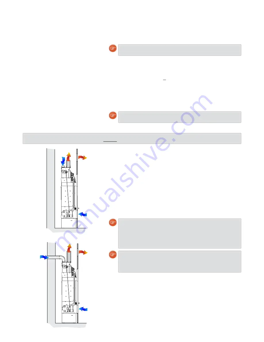
Figure 3

Figure 4

Chimney flue connection independent of indoor air 


(room-sealed appliance)

If the appliance is operated independently of indoor air, the following instruc-
tions are also to be observed:


the chimney flue must be sealed at the pipe connection by means of a tem-
perature resistant sealant. 


the flue pipe must have a gas-proof connection to the chimney and must 
be sealed by means of an appropriate rope seal and a temperature resistant 
sealant (e.g. heat-resistant silicone). 

air intake

air intake

exhaust gas

exhaust gas

convection air 
outlet

convection air 
outlet

air intake / convec-
tion air outlet

convection air 
outlet

Outdoor air supply for combustion 

(Figure 4)


the air for combustion is only slightly pre-heated!


Max. length 4 m with 3 bends. 

Air supply for combustion via the room where


the appliance is located 

(Figure 3)


the air for combustion is pre-heated.


It is necessary to ventilate the room at regular intervals or to provide a 
permanent opening for ventilation to the outside.

Summary of Contents for Aqua Insert+P

Page 1: ...Aqua Insert P Issued November 2010 with pellet burner Independent of indoor air DEPENDENT on indoor air Operating Manual with installation instructions GB...

Page 2: ...g capacity of the floor 13 Room temperature and ambient temperature humidity 13 18 Operation 14 Accessories supplied by the manufacturer 14 Closing the heating door 14 Adjustment of the air supply 14...

Page 3: ...prox 1 to 2 kg When adding more firewood open the door slowly and first allow the flue gas to escape up the chimney By doing this you prevent the flue gas from entering the room Bear in mind that cert...

Page 4: ...e firepla ce Only clean and properly adjusted appliances work efficiently Only install original spare parts provided by your local specialist dealer or by our company Parts that are subject to wear an...

Page 5: ...open and closed water heating systems up to 349 kW 300000 kcal h with thermostatic safety device DIN 4751 Part 4 Safety devices for heating systems with flow temperatures of up to 120 C closed water...

Page 6: ...n 17 Pellet burner ash drawer 19 Hopper safety guard 20 Pellet burner control panel 21 Pellet burner door 23 Induced draught fan 24 Combustion air supply pellet burner 25 Flow connection line 26 Hoppe...

Page 7: ...for the firewood The heat is emitted via the surface of the heat exchanger and the external sur faces of the appliance An induced draught fan corresponding to the amount of fuel and the combustion ai...

Page 8: ...appliance and the chimney can occur Furthermore the combustion of coal and similar fuels is not permitted The ap pliance has not been tested for use with these fuels therefore damage to the appliance...

Page 9: ...with re circulated air operation With ducted extractor hoods an adequate supply of air must be ensured by me ans of separate safety equipment e g contact switches on the windows negative pressure mon...

Page 10: ...and must be protected against wind The air duct must be at least 100 mm in diameter If rectangular pipes are em ployed an appropriate cross section must be maintained According to the regulations for...

Page 11: ...r the installation of the appliance The HVAC installer conducting the inspections for fire safety shall bear the responsibility The following safety clearances to combustible items movable wooden wall...

Page 12: ...drain funnel Should the thermal discharge safety valve drip the seal and valve seat must be cleaned The calcification state of the safety devices must also be checked at least once a year For this rea...

Page 13: ...ance in an emergency We strongly recommend installing a smoke or fire detector that interrupts the power supply of the appliance in an emergency The appliance is designed to operate only from a 230 V...

Page 14: ...owing factors with regard to a clean window 1 Optimum chimney draught For the air supply the chimney draught and the length of the supply line play a decisive role Certain weather conditions especiall...

Page 15: ...me The following table 3 shows the recommended amount of fuel to be added for the rated heat output If this amount is exceeded overheating and consequent damage can result Heating When only embers are...

Page 16: ...es and to switch from one adjustment point to the next in the adjustment le vels To acknowledge error messages by pressing and holding the button approx 2 seconds 20 Operation of the pellet burner Set...

Page 17: ...ttings Menu 22 Settings Menu To enter the main menu from the top level of the menu press the OK button once Settings Appliance settings Information Display Information about the appliance and its comp...

Page 18: ...ther the internal clock is used for switching the appliance on and off Automatic operation determines whether the appliance is operated manually standard setting OFF or whether the internal clock is u...

Page 19: ...ntry of the service code and enter the correct service code Press button twice to return to the top level of the menu To confirm cleaning work or maintenance work that has been performed on the applia...

Page 20: ...adjustment range of the pellet burner Boiler set point temperature WINTER 75 C Boiler set point temperature SUMMER 65 C 24 Information menu 24 Information menu To enter the menu INFORMATION from the m...

Page 21: ...ON OFF OFF Blower off Current value ON OFF OFF Motor off ON OFF OFF Ignition off ON OFF OFF Pump off ON OFF OFF Motor off Press button three times to return to the top level of the menu Appliance SW V...

Page 22: ...door become very hot when the stove is in use tem peratures up to 300 C Make sure that these parts are not touched when the appliance is in operation Keep the firebox door closed at all times even if...

Page 23: ...ing heating with pellets If more firewood is loaded while the appliance is being heated with pellets the appliance first switches to operation with firewood The display Appliance ON as well as the ope...

Page 24: ...er 250 operating hours Figu re 60 After the cleaning work has been performed the display is reset by using the service code CLEANING and timing restarts for the next cleaning For details how to reset...

Page 25: ...vacuum cleaner Allow the appliance to cool down completely and only use a vacuum cleaner with an Ash Box accessory FIRE HAZARD Cleaning of painted surfaces Wipe painted surfaces with a damp cloth do...

Page 26: ...the grate lifter to remove the ash pan towards the front 2 3 and empty it and clean the ash chamber Pellet burner ash pan Open the door of the pellet extension and pull out the ash drawer Figure 69 E...

Page 27: ...of paper in the stove and allow it to burn out The fuel used is too smoky moist or of poor quality See FUELS on page 8 Heating gas flue or chimney excessively sooty or blocked As soon as possible thor...

Page 28: ...e boiler to cool off and reset temperature limiter manually Failure of heating circuit pump Output of appliances radia tors has been reduced pos sibly thermostat valve Open the appliance if it occurs...

Page 29: ...nician BOILER SENSOR UB Boiler sensor fault Cause see flame sensor UB Remedy see flame sensor UB BOILER OVERHE ATED Overheating the preset boiler temperature limit 90 C was exceeded Cause see Temperat...

Page 30: ...mber 19344 Certificate Holzenergie Schweiz Nr Nr 0135 Dimensions installation dimensions Width x height x depth mm 855 x 1830 x 493 with panelling optional Width x height x depth mm 1075 x 1875 x 524...

Page 31: ...12 6 185 5 123 5 51 12 5 134 28 5 69 25 5 68 15 5 21 4 49 5 34 5 16 Return flow in blue thermal safety valve inlet in green Flow in red Supply of combustion air oval 10 cm Flue pipe connection diamet...

Page 32: ...3 4 7 6 5 PE 7 PE PE 6 5 4 3 PE 1 2 3 4 9 5 PE 10 PE PE blue Earthing brown Mains connection Serial input output RS 232 Maintenance Update Fuse Micro fuse 5 x 20 mm 2 5 A T Ceramic body Control panel...

Page 33: ...reduce output stove on off only information only information only information scroll with UP DOWN only information scroll with UP DOWN settings from customer reset with OK brand with OK selection wit...

Page 34: ...check your appliance and establish whether the warranty claim is justified If yes we will decide in which way the defect should be corrected In the event of a repair we will have it carried out corre...

Page 35: ...Seite 35...

Page 36: ...FF 13 45 NO PELLETS Output OK Appliance ON 13 45 Burner ON Output OK Appliance ON 13 45 Burner ON Output Press once Press once Press once Press once Press and hold for 2 seconds Press buttons simultan...

Reviews: