background image


Operation Manual Network Camera logiware IPC1901A 

56 

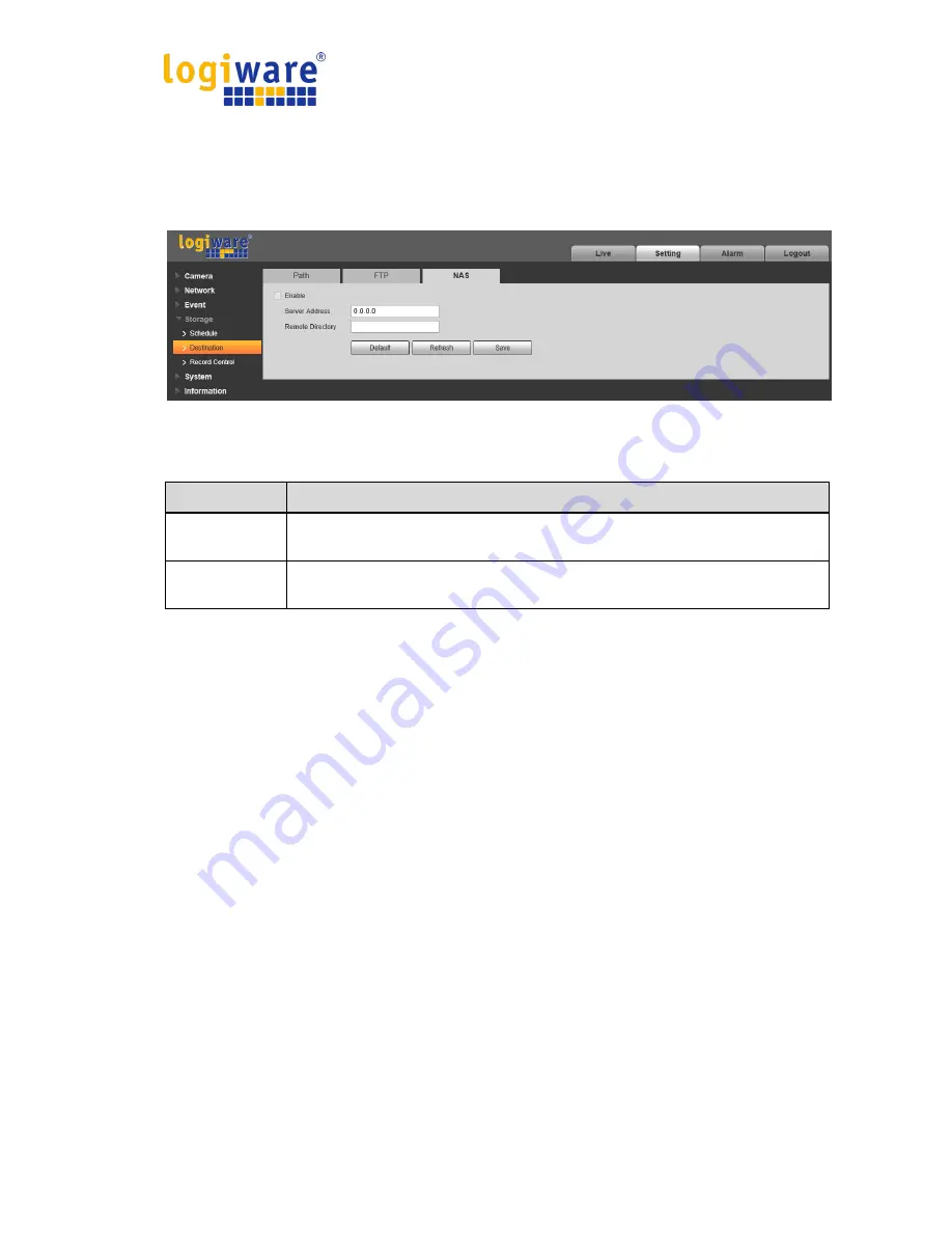
3.4.2.3 NAS 

You need to check the box to enable the NAS function. Select NAS storage, fill in NAS server 

address and corresponding store path, then you can store video file or pictorial information in the 

NAS server. See Figure 3-47. 


Figure 3-47 


Parameter 

Function 

Server 
Address 

Set IP address of NAS server. 

Remote 
Directory 

Set storage directory, videos and pictures can be stored in to corresponding 

server directory. 


Summary of Contents for IPC1901A

Page 1: ...a logiware IPC1901A Default DHCP Fallback IP 192 168 178 178 Username admin Password admin logiware gmbh Alfred Mozer Str 51 D 48527 Nordhorn Tel 49 0 5921 7139925 Fax 49 0 5921 7139929 Internet https...

Page 2: ...Ratio 10 2 4 5 Fluency Adjustment 10 2 4 6 Rules Info 10 3 Setting 11 3 1 Camera 11 3 1 1 Conditions 11 3 1 2 Video 21 3 2 Network 27 3 2 1 TCP IP 27 3 2 2 Port 29 3 2 3 PPPoE 30 3 2 4 DDNS 31 3 2 5...

Page 3: ...re IPC1901A iii 3 5 System 58 3 5 1 General 58 3 5 2 Account 60 3 5 3 Safety 64 3 5 4 Default 75 3 5 5 Import Export 75 3 5 6 Auto Maintenance 76 3 5 7 Upgrade 76 3 5 8 Version 77 3 5 9 Log 77 3 5 10...

Page 4: ...ow its IP address The default IP address is 192 168 178 178 if there is no DHCP server in the network The user can use the configuration tool to find the IP address of the network camera The configura...

Page 5: ...are shown as follows Open Internet Explorer and enter the address of the network camera in the address bar The default IP address is 192 168 178 178 if there is no DHCP server in the network After suc...

Page 6: ...fter successful login you may see the interface shown as in Figure 1 4 Figure 1 4 Click on Please click here to download and install the plug in The system pops up warning information to ask you wheth...

Page 7: ...on Manual Network Camera logiware IPC1901A 4 You must either run or save the file to local and install it Follow the following steps Click on run you will see Figure 1 6 and Figure 1 7 Figure 1 6 Figu...

Page 8: ...Network Camera logiware IPC1901A 5 When plug in installation completes the installation page closes automatically The web end will refresh automatically and then you can view video captured by the ca...

Page 9: ...C1901A 6 2 Live After you logged in you can see the live monitor window See Figure 2 1 Figure 2 1 There are four sections Section 1 Encode setup bar Section 2 System menu Section 3 Window function opt...

Page 10: ...and click again to disable it Generally for storage and monitor Sub Stream Click it to enable Sub Stream video monitoring and click again to disable it When network bandwidth is insufficient it subst...

Page 11: ...in In the non original status you can drag the zoom in zone in specified range Right click mouse to restore previous status Click it you can use the middle button of the mouse to zoom in out the video...

Page 12: ...This interface is on the top right pane Please refer to the following sheet for detailed information Parameter Function Video setup It is to adjust monitor video brightness Note All the operations he...

Page 13: ...lick it to go to full screen mode Double click the mouse or click the Esc button to exit the full screen 2 4 4 Width and Height Ratio Click it to restore original ratio or suitable window 2 4 5 Fluenc...

Page 14: ...shown in Figure 3 1 Figure 3 1 Step 2 Set picture parameters please refer to the following sheet for more details about parameter setting Parameter Note Style It is to set the picture style which inc...

Page 15: ...ia nonlinear adjustment mode The bigger the value is the brighter the picture becomes and on the contrary it is opposite Mirror After mirror is enabled the monitoring image will be displayed invertedl...

Page 16: ...sure mode Note When Anti flicker is Outdor the exposure mode can be set as gain priority or shutter priority mode Different devices have different exposure modes please refer to the actual interface I...

Page 17: ...eter when 3D NR is enabled The bigger the grade is the better NR effect it can realize Step 3 Click Save to complete the parameter configuration of camera exposure 3 1 1 3 Backlight Backlight mode can...

Page 18: ...tem can realize exposure upon the selected area after it set customized area which is to make the image of the selected area reach appropriate brightness When the Mode is set as WDR it will lower the...

Page 19: ...e without artificial light which is to make the image color normal When the Mode is set as Street Lamp the system can auto compensate white balance to the outdoor scene at night which is to make the i...

Page 20: ...tails Parameter Note Mode It is to set the camera image displayed as color or black white mode Note The setting of Day Night Mode is not affected by the setting of Profile Management It includes the f...

Page 21: ...he device is equipped with IR light Step 1 Select Setting Camera Conditions IR Light and the system will display the interface of IR Light which is shown in Figure 3 6 Figure 3 6 Step 2 It is to set I...

Page 22: ...ain wide angle which is to avoid near overexposure Meanwhile it can manually set light compensation to slightly adjust the brightness of IR light When the mode is set as Off it will not enable the IR...

Page 23: ...s night for example if it sets 0 00 12 00 as day 12 00 24 00 as night then the system will monitor by adopting corresponding configuration in different periods Figure 3 9 Step 3 Click Save to complete...

Page 24: ...b stream 1 and sub stream 2 at the same time Encode mode There are three options H 264H high profile standard H 265 main profile standard and MJPEG encode Resolution There are multiple resolutions You...

Page 25: ...enable watermark function After the watermark function is enabled you can check if the video is tampered via verifying watermark character Watermark Character It is the character of watermark verifica...

Page 26: ...Operation Manual Network Camera logiware IPC1901A 23 3 1 2 3 Video Overlay The video overlay interface is shown as in Figure Figure 3 12 to Figure 3 15 Figure 3 12 Figure 3 13...

Page 27: ...ask the specified video in the monitor video System max supports 4 privacy mask zones Time Title You can enable this function so that system overlays time information in video window You can use the m...

Page 28: ...eft and align right Refresh Set privacy mask channel title time title location overlay and save the change You can click on Refresh to see effect Default Click it to restore default config Save Click...

Page 29: ...Here you can set snap image saved path and the record storage path The default monitor image path is C Users admin WebDownload LiveSnapshot The default monitor record path is C Users admin WebDownloa...

Page 30: ...ct the Ethernet port Default is wired Please note you can modify the default Ethernet card if there is more than one card Mode There are two modes static mode and the DHCP mode Select DHCP mode it aut...

Page 31: ...work camera and the PC in the same LAN Step 2 Get the physical address from the label of the network camera Step 3 Go to the Run interface and then input the following commands arp s IP Address MAC pi...

Page 32: ...5524 The default value is 80 You can input the actual port number if necessary RTSP port The default value is 554 Please leave blank if use default User uses QuickTime or VLC can play the following fo...

Page 33: ...net Service Provider and click Enable The network camera will automatically establish network connection in the mode of PPPoE after it is enabled after it is successful the IP of the IP Address will b...

Page 34: ...changed When the device connects to WLAN you should disable UPnP Figure 3 21 Please refer to the following sheet for detailed information Parameter Function Server Type You can select DDNS protocol fr...

Page 35: ...f necessary Anonymity For the server which supports the anonymity email function it won t display the information of the sender User Name The user name of the sender email account Password The passwor...

Page 36: ...Before the email test please save the email setup information 3 2 6 UPnP It allows you to establish the mapping relationship between the LAN and the public network Here you can also add modify or rem...

Page 37: ...ormation from other device You can use the browse of the Bonjour service in the same LAN to search the network camera device and then access if you do not know the network camera information such as I...

Page 38: ...the outer Note Open preview streaming media protocol select multicast and monitor via multicast format Here you can set multicast address and port You also need to go to Live interface to set the prot...

Page 39: ...Quality of Service is network security mechanism It is a technology to fix the network delay and jam problem and etc For the network service the quality of service includes the transmission bandwidth...

Page 40: ...eet for detailed information Parameter Function Real time monitor The value ranges from 0 to 63 The router or the switcher can provide different service for various data packets Command The value rang...

Page 41: ...ard describes network video mode interface data type and data interaction mode ONVIF Standard s aim is to achieve a network video frame agreement and makes the network video products including video f...

Page 42: ...vent Video Detection Motion Detection and the system will display the interface of Motion Detection which is shown in Figure 3 29 Figure 3 29 Step 2 Select Enable to enable motion detection function S...

Page 43: ...the smaller the threshold is the easier it is to generate motion detection the entire video image is the valid area of motion detection by default Note Different colors represent different areas each...

Page 44: ...o set the valid area of motion detection according to the actual situation and it can set its sensitivity and threshold respectively The higher the sensitivity is the easier it is to trigger motion de...

Page 45: ...e numerical value or press the left mouse button to drag on the setup interface to set There are six periods to be set every day select the check box in front of the period and then the period is vali...

Page 46: ...or more details Parameter Function Working Period Note It is to set the alarm period it can enable alarm event only during the period range which has been set 1 Click Setup and the system will pop out...

Page 47: ...hen alarm occurs and ends User can set email address in Network SMTP Snapshot You need to check the box here so that system can backup motion detection snapshot file You shall set snapshot period in S...

Page 48: ...ference of brightness value between target and background can t be less than 10 gray levels Make sure the target appears at least over 2 seconds continuously in the field the movement distance has to...

Page 49: ...e some space on both sides of the warning line when setting the warning line please do not set the warning line near the obstructions Application scene it can be applied to the scene with sparse targe...

Page 50: ...ace to set There are six periods to be set every day select the check box in front of the period and then the period is valid Select week number it selects Sunday by default if it selects the whole we...

Page 51: ...for target movement for the area periphery if it is to detect enter exit event which is similar to the warning line Application scene it can be applied to the scene where the target is sparse and the...

Page 52: ...k then it means the setup can be applied to the whole week you can also select the check box in front of the week number to implement independent setting for some days 3 Click Save to complete the set...

Page 53: ...mality Abnormality includes Disconnection IP Conflict and Illegal Access Figure 3 36 When login password keep been wrong for a few times unauthorized access alarm occurs Allow login error times as whe...

Page 54: ...Schedule Record schedule steps Step 1 Click on Record Schedule see Figure 3 38 Figure 3 38 Step 2 From Monday to Sunday select record time click on setup on the right see Figure 3 38 Set period accord...

Page 55: ...40 Green color stands for the normal record snapshot Yellow color stands for the motion detect record snapshot Figure 3 40 Step 4 In record schedule interface click on OK System prompts it is successf...

Page 56: ...can add or delete two types of snapshot schedule Normal and Motion Note Period setup can be done by dragging in snapshot schedule interface while not releasing left mouse Figure 3 42 Step 2 Click on O...

Page 57: ...Step 2 Select date to set as holiday The selected date will be highlighted in yellow Step 3 Check Record Snapshot click on Save System prompts it is successfully saved Step 4 Check Record Schedule Sn...

Page 58: ...ce Please check the box to enable the save functions Figure 3 45 Please refer to the following sheet for detailed information Parameter Function Event Type It includes scheduled and motion detection F...

Page 59: ...age fill in NAS server address and corresponding store path then you can store video file or pictorial information in the NAS server See Figure 3 47 Figure 3 47 Parameter Function Server Address Set I...

Page 60: ...the four seconds video in the buffer The record begins from the fifth second Note Configure pre record time when alarm or motion detection occurs if there is no record system will record the precedin...

Page 61: ...s in Figure 3 49 Figure 3 49 Please refer to the following sheet for detailed information Parameter Function Device Name It is to set device name Note Different devices have different names Language Y...

Page 62: ...of the device Current Time It is to set system time It becomes valid after you set Sync PC You can click this button to save the system time as your PC current time DST Enable Here you can set both be...

Page 63: ...remove user and modify user name See Figure 3 51 Figure 3 51 Enable anonymity login Enable anonymity login and input IP No username or password is required you can log in by anonymity with limited rig...

Page 64: ...ssword It is to modify the user password You need to input the old password and then input the new password twice to confirm the new setup Please click the OK button to save Please note the password r...

Page 65: ...ove group modify group password and etc The interface is shown as in Figure 3 54 Figure 3 54 Add group It is to add group and set its corresponding rights See Figure 3 55 Please input the group name a...

Page 66: ...etwork Camera logiware IPC1901A 63 Figure 3 55 Modify group Click the modify group button you can see an interface is shown as in Figure 3 56 Here you can modify group information such as remarks and...

Page 67: ...me specified IP MAC user can access the network camera You can add IP address or IP segment If you do not check the box here it means there is on access limit Here you can add IP address and MAC addre...

Page 68: ...data and provide safeguard for user information and device security with reliable and stable technical means Step 1 Create certificate or upload the signed certificate Please refer to the following st...

Page 69: ...formation click Create after filling in It will show the prompt of Create Successfully which means the server certificate has been successfully created Note Make sure the IP or domain name is the same...

Page 70: ...re 3 61 5 Click Download It will pop out the dialog box of Save as save the file into the computer Figure 3 62 6 Double click the downloaded icon of RootCert cer The system will display the informatio...

Page 71: ...Operation Manual Network Camera logiware IPC1901A 68 Figure 3 63 7 Click Install Certificate and it will pop out the interface of Certificate Import Wizard which is shown in Figure 3 64...

Page 72: ...Operation Manual Network Camera logiware IPC1901A 69 Figure 3 64 8 Click Next Select Trusted Root Certification Authorities which is shown in Figure 3 65...

Page 73: ...Operation Manual Network Camera logiware IPC1901A 70 Figure 3 65 9 Click Next The system will display the interface of Completing the Certificate Import Wizard which is shown in Figure 3 66...

Page 74: ...Operation Manual Network Camera logiware IPC1901A 71 Figure 3 66 10 Click Finish and it will pop out the dialog box of Security Warning which is shown in Figure 3 67...

Page 75: ...log box of Import Successful click Ok to complete downloading certificate which is shown in Figure 3 68 Figure 3 68 Please refer to the following steps if you select Install Signed Certificate 1 Selec...

Page 76: ...step 6 11 for more details 4 Check Enable HTTPs click Save The system will display the dialog box of Need to reboot the device and then the configuration is valid Figure 3 70 5 Use HTTPs Use HTTPs to...

Page 77: ...Operation Manual Network Camera logiware IPC1901A 74 Figure 3 71 Note xx xx xx xx is corresponding to your IP or domain name...

Page 78: ...some information such as network IP address account and so on Figure 3 72 3 5 5 Import Export The interface is shown as in Figure 3 73 Figure 3 73 Please refer to the following sheet for detailed info...

Page 79: ...delete old files function you need to set the file period Figure 3 74 Parameter Function Auto Reboot Check it and set auto reboot time Auto Delete Old Files Check it and set period within 1 31 days 3...

Page 80: ...sion The version interface is shown as in Figure 3 76 Here you can view system hardware features software version release date and etc Please note the following information is for reference only Figur...

Page 81: ...he drop down list and then click search button to view the list You can click the stop button to terminate current search operation Log information You can select one item to view the detailed informa...

Page 82: ...triggered Scene Changing System will record alarm info when triggering scene changing Operation Prompt When alarm is triggered there will be s inmain menu of alarm interface and system automatically r...

Page 83: ...rence only Slight difference may be found in user interface All the designs and software here are subject to change without prior written notice All trademarks and registered trademarks mentioned are...

Page 84: ...amera logiware IPC1901A 81 logiware gmbh Alfred Mozer Str 51 D 48527 Nordhorn Germany Tel 49 0 5921 7139925 Fax 49 0 5921 7139929 Internet https www go1984 com E Mail Sales sales logiware de E Mail Su...

Reviews: