


Page 4-3
FPU-32 Feeder Protection Unit
Rev.
2-A-103014
Operation and Setup
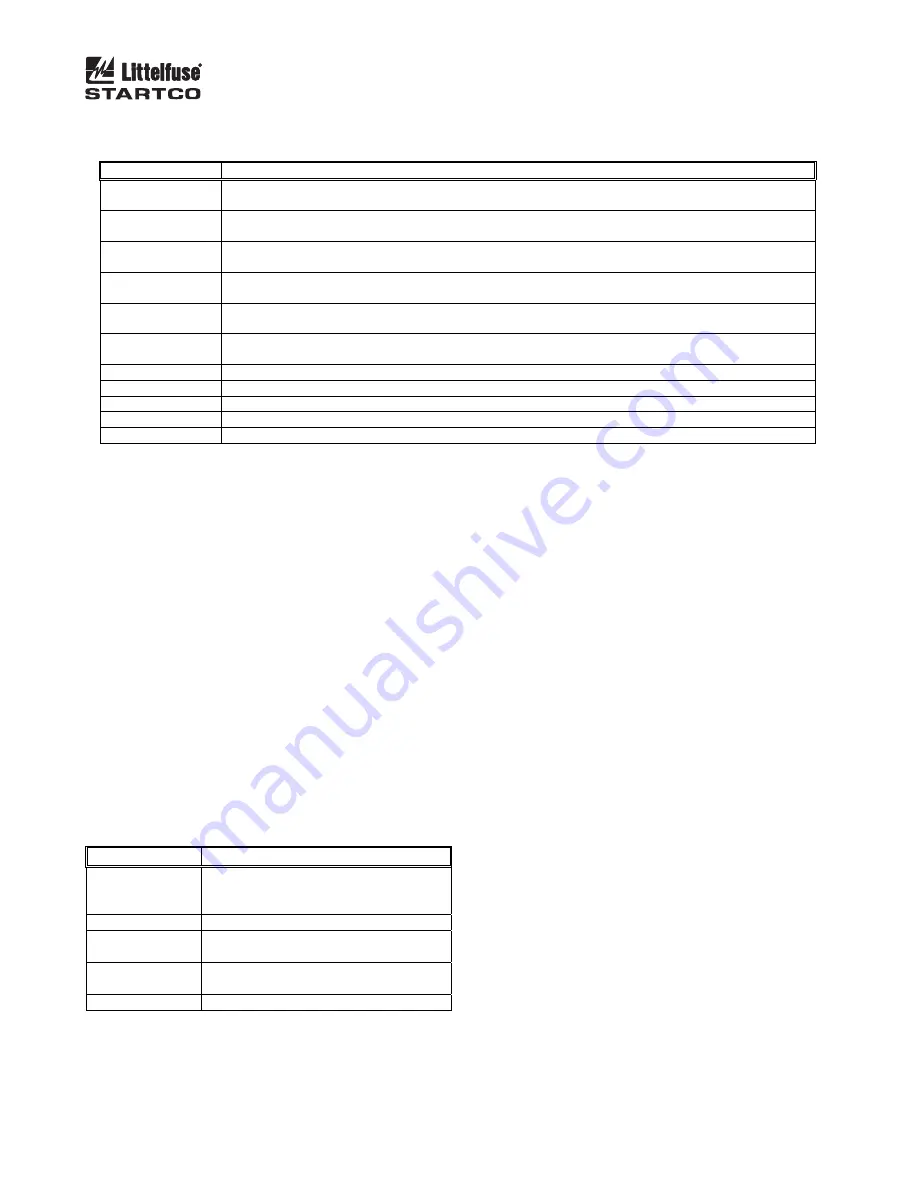
TABLE 4.2 O
UTPUT
-R
ELAY
F
UNCTIONS
F
UNCTION
A
SSIGNMENT OR
A
CTION
Trip1
Relay operates when a trip occurs in a protective function assigned Trip1, Trip1&2, Trip1&3, or
Trip1,2&3 trip action. Fail-safe or non-fail-safe mode selection is active.
Trip2
Relay operates when a trip occurs in a protective function assigned Trip2, Trip1&2, Trip2&3, or
Trip1,2&3 trip action. Fail-safe or non-fail-safe mode selection is active.
Trip3
Relay operates when a trip occurs in a protective function assigned Trip3, Trip1&3, Trip2&3, or
Trip1,2&3 trip action. Fail-safe or non-fail-safe mode selection is active.
Alarm1
Relay operates when an alarm occurs in a protective function assigned Alarm1, Alarm1&2, Alarm1&3, or
Alarm1,2&3 alarm action. Fail-safe or non-fail-safe mode selection is active.
Alarm2
Relay operates when an alarm occurs in a protective function assigned Alarm2, Alarm1&2, Alarm2&3, or
Alarm1,2&3 alarm action. Fail-safe or non-fail-safe mode selection is active.
Alarm3
Relay operates when an alarm occurs in a protective function assigned Alarm3, Alarm1&3, Alarm2&3, or
Alarm1,2&3 alarm action. Fail-safe or non-fail-safe mode selection is active.
Current
Relay is energized when current is greater than 2% of CT-primary rating.
Trip1 Pulse
(1)
Trip1 energizes relay for the time duration specified by the
RY Pulse Time
set point.
Network Run1
Relay is energized by a network “Run1 Set” command and de-energized by a “Run1 Clear” command.
Watchdog
Relay is energized when the FPU-32 is operating properly.
None No
assignment.
(1)
Assign this function to only one relay. Non-fail-safe operation only.
4.2.6 D
IGITAL
I
NPUT
Menu:
Setup
|
Digital Input
|
DIN1 Function
Menu:
Setup
|
Digital Input
|
DIN1 Trip Delay
The digital input can be assigned to one of the
functions listed in Table 4.3.
When assigned to the
Trip1
function, the
DIN1 Trip
Delay
set point is enabled. A trip occurs if the digital-
input voltage is removed for the time specified by the
DIN1 Trip Delay
.
When assigned to
Reset
, trips can be reset using an
external reset switch. The
Reset
input is a “one-shot”
reset and requires a transition from open to closed.
Maintaining a reset switch closure does not inhibit trips.
When assigned to
Program Enable,
the password
protection function is disabled and program access is a
function of the digital-input state.
When assigned to
Set-Point Group
, one of two groups
is selected. The digital-input selection has priority over
the
Setup
System Ratings
Set-Point Group
setting.
TABLE 4.3 D
IGITAL
-I
NPUT
F
UNCTIONS
F
UNCTION
S
TATE
(1)
Trip1
1 = No Trip1
0 = Trip1 (Delay Selectable, Reset
Required)
Reset
1 = Reset Trips
Program Enable
(2)
1 = Program Changes Allowed
0 = No Program Changes Allowed
Set-Point Group
1 = Group2 Set Points
0 = Group1 Set Points
None
No Assignment (Default)
(1)
1 = 24-Vdc applied, 0 = 24-Vdc not applied.
(2)
Password is disabled.
4.2.7 A
NALOG
O
UTPUT
Menu:
Setup
|
Analog Output
The 20-mA analog output can be programmed for one
of the parameters shown in Table 4.4.
The analog output is factory calibrated for zero equals
4.0 mA and full scale equals 20.0 mA.
If adjustment is required use the
Analog Output
menus.
Zero
Calibration:
Select
Zero
in the
Output Parameter
menu.
Measure the output current and adjust the
Zero
Calibrate
setting for the desired output. The
calibration number for 4 mA will be in the range of
100 to 110.
Full-Scale
Calibration:
Select
Full Scale
in the
Output Parameter
menu.
Measure the output current and adjust the
FS Calibrate
setting for the desired output. The
calibration number for 20 mA will be in the range of
540 to 550.
Calibration numbers are not changed when factory
defaults are loaded or during a firmware update.


