


Page 3-4
FPU-32 Feeder Protection Unit
Rev.
2-A-103014
System
Wiring
3.2.2.1 S
TANDARD
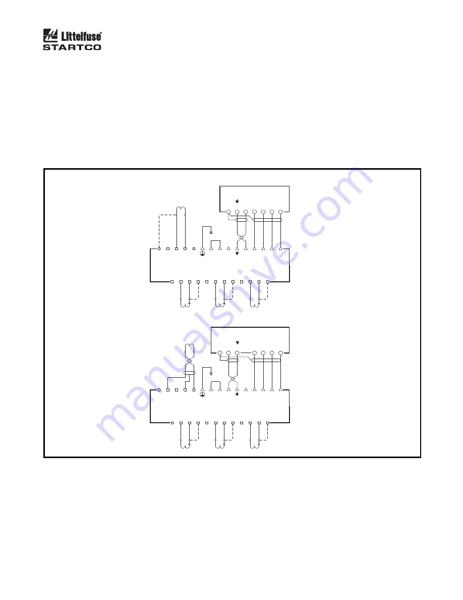
Standard connections with earth-fault CT’s are shown in
Fig. 3.6. Dotted lines indicate 1-A-CT connections. Use
shielded cable for EFCT-1 or EFCT-2 connections. Ensure
only current-carrying phase conductors pass through the
earth-fault-CT window and that ground conductors do not.
3.2.2.2 R
ESIDUAL
E
ARTH
-F
AULT
The residual earth-fault connection is shown in
Fig. 3.7 (a). Dotted lines indicate 1-A-CT connections.
Use three identical CT’s for this connection.
This connection is a legacy from FPU-16 applications.
The FPU-32 calculates residual current. See Section 4.2.2.
3.2.2.3 T
WO
-CT
The two-CT connection is shown in Figs. 3.7 (b) and
3.7 (c). Dotted lines indicate 1-A-CT connections. Since
this connection derives the current in the unmonitored
phase, this connection should be used only in retrofit
applications where it is not possible to install a third CT.
EFCT-X
a) STANDARD CONNECTION
FPU-32
1-A OR 5-A
EARTH-FAULT
CT
1A
5A
S
H
E
F
C
O
M
C
B
A
29
21
22
16
15
14
13
BRO
WN
BLUE
GREEN
RED
WHITE
BLA
CK
27
26
25
24
23
22
21
20
19
18
17
16
15
14
13
C
O
M
C
B
A
E
F
2
E
F
1
Y
X
E
S
5
R
1
R
S
5
1
R
S
5
1
R
S
5
1
1
2
3
4
5
6
7
8
9
10
11
12
5A
5A
5A
1A
1A
1A
CT A
CT B
CT C
S TERMINALS ARE GROUNDED
THROUGH TERMINAL 22
b) STANDARD CONNECTION WITH EFCT-1 OR EFCT-2
S
H
E
F
C
O
M
C
B
A
29
21
22
16
15
14
13
FPU-32
BRO
WN
BLUE
GREEN
RED
WHITE
BLA
CK
C
O
M
C
B
A
E
F
2
E
F
1
Y
X
E
S
5
R
1
27
26
25
24
23
22
21
20
19
18
17
16
15
14
13
R
S
5
1
R
S
5
1
R
S
5
1
1
2
3
4
5
6
7
8
9
10
11
12
5A
5A
5A
1A
1A
1A
CT A
CT B
CT C
MPU-CIM
MPU-CIM
S AND E TERMINALS ARE GROUNDED.
S THROUGH TERMINAL 22,
E THROUGH TERMINAL 18.
FIGURE 3.6 MPU-CIM Standard Connections.


