


Page 14
Installation & Use – English Guide
LINDY ELECTRONICS LTD
3. Using the LINDY CPU Switch Junior
This section explains the general operation of the LINDY CPU Switch Junior. We recommend that
you read this section before starting to use the product.
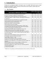
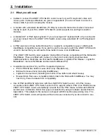
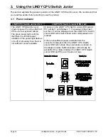
3.1 Power
indicator
LINDY CPU Switch Junior 2 & 4
LINDY CPU Switch Junior OSD 4 & 8
The LINDY CPU Switch Junior
draws its power from the attached
CPUs via the keyboard cables.
The green power light confirms
that there is sufficient power
available. If the power light flashes
or is off continuously then there is
not sufficient power available.
At power on the LINDY CPU Switch Junior OSD selects
PC number 1 and displays ‘1’. If a password has been
set then ‘P’ will be displayed and the LINDY CPU Switch
Junior OSD will remain locked until a valid password is
entered.
If there is insufficient power available from the
connected computers then the LINDY CPU Switch
Junior OSD will indicate the power status as shown in
the diagram below. Sufficient power will normally be
available if the cables between the LINDY CPU Switch
Junior OSD and PCs are 3 metres or less.


