
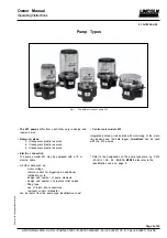


Subject
to
change
without
notice
Owner Manual
Operating Instructions
2.1A-30004-A02
Page 18 of 36
LINCOLN GmbH & Co. KG Postfach 1263 D-69183 Walldorf Tel +49 (6227) 33-0 Fax +49 (6227) 33-259
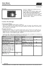
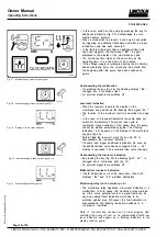
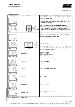
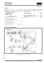
Setting and Operation of the Control
Three possible modes of operation and settings can be
selected on the membrane key pad.
Display mode
As soon as voltage is applied to pump P 233, the
control is automatically in the
display mode.
The
right
segment
on the display is illuminated (On).
Normally, the display is dark. Only the functions (seg-
ment, circulating segment display) or malfunctions
(* Er *, or * LL *) appear illuminated in the display.
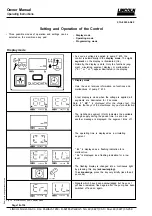
Display mode
- Here the user receives information on functions and
malfunctions of pump P 233.
- A test display is made when the voltage is applied, all
segments are illuminated for 2 seconds.
Note: If
* EP *
is displayed after the display test, this
indicates that keys of the membrane key pad are defective.
- The right-hand segment (On/h) indicates the available
voltage supply during the pause time. As soon as
another message is displayed, the segment turns off.
- The operating time is displayed as a circulating
segment.
- *
Er *
is displayed as a flashing indication for a
malfunction.
-
* LL*
is displayed as a flashing indication for a low
level.
- The flashing display is changed into a continuous light
by pressing this key
(acknowledging)
.
To
acknowledge,
press the key only briefly (less than 2
seconds).
Signals which have been acknowledged but have not
yet been remedied, flash again after the pump has been
switched off and on again.
4288a01
4207a99
4227a99
4279a00
4209a99
4211a99
4210a99
4214a99
4213a99
4212a99
Fig. 34 - Membrane key pad in display mode
- Display mode
- Operating mode
- Programming mode