


Subject
to
change
without
notice
Owner Manual
Operating Instructions
2.1A-30004-A02
LINCOLN GmbH & Co. KG Postfach 1263 D-69183 Walldorf Tel +49 (6227) 33-0 Fax +49 (6227) 33-259
Page 11 of 36
4159a98
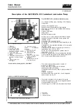
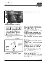
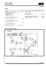
Fig. 12 - Sectional view: Adjustable pump element
1 - Adjusting spindle SW 16 (with over flats)
3 - Pump element body
6 - Control piston
2 - Counter nut SW 24
4 - Gasket
7 - Delivery piston
5 - Pump cylinder
S - Size
Setting of the output
* Unscrew the coupling nut for fixing the pressure relief
valve.
* Loosen counter nut (2, fig. 12) while holding in position
pump element body (3) by means of a second wrench.
* Adjust the regulating spindle (1) by means of a wrench,
see output diagram (fig. 13)
* The size S (see fig. 12) for the desired lubricant output
can be ascertained by using the delivery diagram shown
in fig. 13.
Retrofit adjustment of maximum lubricant output:
Note: In order to ensure that the lubricant output setting will
be as exact as possible, first the actual size S of the max.
lubricant output must be ascertained as follows. The measu-
red difference to the nominal value 29 mm must be conside-
red for all other setting values (e.g. ± 0,1).
* Unscrew the adjusting spindle (1, fig.12) out of the pump
element body (3) until S is approx. 30 mm.
* Screw counter nut (2) onto stop collar of the adjusting
spindle (1).
* Screw adjusting spindle (1) with counter nut (2) into
pump body (3) until stop.
Adjustment of small lubricant output:
* Before the pump element can be adjusted to a small
lubricant output, the size S for max. lubricant output
must be ascertained, and the difference to the nominal
value 29 mm must be transferred to any desired setting
between 25.5...28.5 mm.
* Dimension S must be adjusted to the desired value in
accordance with the delivery diagram (fig. 13).
Note: At maximum setting, S is 29±0.1 mm.
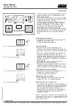
Fig. 13 - Delivery diagram
4179a99
A - Lubricant output in cm³/minS - Size
B - Lubricant output in cm³/stroke