
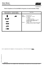


Subject
to
change
without
notice
Owner Manual
Operating Instructions
2.1A-30004-A02
LINCOLN GmbH & Co. KG Postfach 1263 D-69183 Walldorf Tel +49 (6227) 33-0 Fax +49 (6227) 33-259
Page 13 of 36
10032618
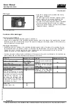
Fig. 17 - Return line connection
Lubricant quantities which cannot be dispensed by the
metering device must be returned to the pump via the
return line connection (fig. 15).
Return Line Connection
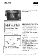
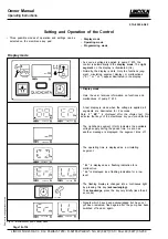
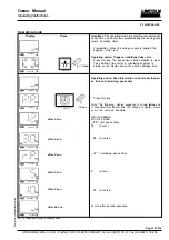
Printed circuit board with data memory
1059a95
Fig. 18 - Time sequence diagram
tB - Working hours
T - Lubrication cycle
tP - Individual pause times
T1 - Stored pause times
T2 - Operating times
The printed circuit board automatically controls the
sequence of the pause and operating times of the 233
centralized lubrication pump as a function of the vehicle
or machine working hours tB (fig. 18).
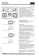
The sequence of the pause and operating times is
activated when the machine contact or driving switch is
switched on, i.e. the centralized lubrication pump is ready
for operation.
A lubrication cycle consists of one pause time and one
operating time. Once the pause time has elapsed, the
operating time starts to run. This lubrication cycle is
repeated permanently after the machine or vehicle has
been put into operation (fig. 18).
During the operating time the pump element dispenses
the lubricant to the lubrication points via progressive
divider valves.
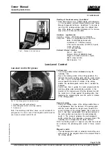
4205a01
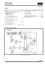
Fig. 19 - Pump 233 with data logger, schematic drawing
1 - Low-level control 4 - Control p.c.b. with data logger
2 - Piston detector 5 - Pump
3 - Membrane key pad 6 - Lubricant divider valve SSV N
Pause time
The pause time
- determines the frequency of the lubrication cycles within
a working cycle;
- is started and stopped via the machine contact or driving
switch
- is adjustable
When the machine contact or the driving switch is
switched off, the pause times which have already elap-
sed are stored and added up by an
electronic data
memory
(EEPROM) until the time which has been set on
the membrane key pad is reached.
After the machine contact or driving switch is switched on
again, the printed circuit board operates from the point
where it had been interrupted.
If the setting is modified within the pause time, the
printed circuit board takes over the new value
automatically on completion of the programming
procedure (see Programming Mode).
The pause time setting may be different for each applica-
tion. It must be adjusted in accordance with the respecti-
ve lubrication cycles (see Programming Mode).
Standard setting: 6 hours.