Lincoln QUICKDATA 233 Owner'S Manual Download Page 16

Subject 

to 

change 

without 

notice

Owner  Manual

Operating Instructions

2.1A-30004-A02

Page 16 of 36

LINCOLN GmbH & Co. KG • Postfach 1263 • D-69183 Walldorf • Tel +49 (6227) 33-0 • Fax +49 (6227) 33-259

4228a01

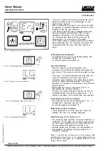
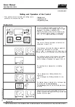
• In  this  case,  switch  on  the  pump  by  pressing  the  key  for

additional  lubrication  (fig.  25).  Acknowledge  the  mal-

function  before  doing  so.

• When  a  malfunction  is  present,  it  can  only  be  cancelled

by  triggering  an  additional  lubrication  and  after  a  proper

lubrication  cycle  has  been  executed.

•  If the fault is still present after an additional lube cycle

has  been  triggered,  the  fault  signal

  *  ER  *

  is  again

displayed  in  the  display  of  the  membrane  key  pad.

• The  monitoring  time  starts  at  the  same  time  as  the

operating  time.  It  is  a  fixed  time  of  30  minutes.

• If  the  voltage  supply  is  interrupted  during  the  monitoring

phase  (operating  time),  the  monitoring  time  starts  from

the  beginning  after  the  pump  has  been  switched  on

again.

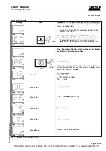
Acknowleding  the  malfunction

• On  pressing  the  key  (fig.  28),  the  flashing  display 

*  Er  *

changes  into  a  continuous  light.

• An  external  signal  lamp  switches  off.

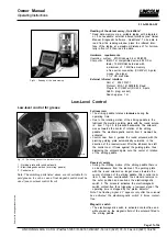
Low-level  indication

• When  the  reservoir  is  empty  the  display  on  the

membrane  key  pad  shows  the  flashing  fault  signal 

*LL  *.

• The  function  of  the  low-level  control  is  described  on  page

17.

• In  the  case  of  a  low-level  indication  the  pump  does  not

switch  off  immediately.  The  current  lube  cycle  is

completed.  Upon  expiration  of  the  pause  time,  the  pump

cannot  be  started  automatically  again.  The  flashing

indication

  *  LL*

  appears  on  the  display  of  the  membrane

key pad (fig. 29)

.

* Before  filling  the  reservoir,  press  the  key,  fig.  30,  to

acknowledge  the  low-level  indication.

* Fill  pump  and  trigger  additional  lubrication.  As  soon  as

the  additional  lube  cycle  has  been  triggered,  the 

„    LL  “

display  is  cancelled.  The  automatic  lube  cycle  resumes.

Acknowleding  the  low-level  indication

• By pressing the key (fig. 30) the flashing light

 *  LL *

  is

changed  into  a  continuous  light  (fig.  31).

• An  external  signal  lamp  switches  off.

Malfunction/  low-level  indication

• If  both  indications  occur  at  the  same  time,  then  both

displays 

*  Er  *

  and

  *  LL*

  will  flash  alternately.

Fig.  27  -  Membrane  key  pad with fault signal

Fig.  28  - Acknowledging  a  flashing  fault  signal  „Er“

4214a99

4211a99

Fig.  29  -  Display  of  a  low-level  indication

4214a99

Fig.  30  - Acknowledging  a  flashing  fault  signal  „LL“

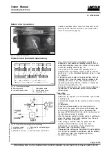
Monitoring relay (on the control p.c.b.)

• The  monitoring  relay  signalizes  a  low-level  indication  or  a

malfunction.  In  both  cases,  the  monitoring  relay  will  pick

up.  Via  a  minus  potential  contact,  a  signal  lamp  can  be

used  as  external  fault  indication  which  has  to  be

switched  against  plus.  Whenever  the  fault  indication  is

acknowledged,  the  flashing  indication  switches  to  a

continuous  indication.

Note:  If    the  fault  has  not  been  put  in  order  properly,  after

switching  the  pump  off  and  on,  an  acknowledged  fault/  low-

level  indication  will  appear  as  a  flashing  indication  in  the

display  window  again.

Fig. 31 - Acknowledged fault signal „LL“

Summary of Contents for QUICKDATA 233

Page 1: ...orf Tel 49 6227 33 0 Fax 49 6227 33 259 Page 1 of 36 4354a01 QuickData Pump 233 with Data Logger Requesting a service page in French Italian Spanish language see page 35 Ordenar manual en espa ol p gi...

Page 2: ...s Industry Machines Commercial Vehicles Building Machinery Agricultural Machines Pump Type Pump QUICKDATA 233 Reservoir 2 l 2XL 2XLFL 2XLBO 4 l 4XLBO 8 l 8XLBO Filling from the bottom 4l 8l with locka...

Page 3: ...ubricant outputs 11 Pressure relief valve 12 Return line connection 13 Printed circuit board with data logger 13 Membrane key pad 15 Page Low level control 17 Adjustment and operation of the control 1...

Page 4: ...g the system must be replaced afterwards Keep QUICKDATA centralized lubrication systems away from sources of heat Adhere to the operating tempera ture Use only original LINCOLN spare parts see Parts C...

Page 5: ...he identification code on page 6 The 233 pumps differ from each other only in design and reservoir size Reservoir sizes 2 l transparent plastic reservoir 4 l transparent plastic reservoir 8 l transpar...

Page 6: ...mber of electric connecting possibilities on pump housing only 2A 1 connection on the left side for power supply external illuminated pushbutton for additional lubrication and fault indication second...

Page 7: ...oints via one divider valve model SSV N and several divider valves model SSV 4355a01 Fig 2 Components of pump 233 1 Reservoir 2 Pump element 3 Pressure relief valve 4 Filling nipple system Emergency l...

Page 8: ...ts such as malfunctions of the centralized lubrication systems faults in the elapse of the operating time low level indications pause times residual pause times of the pump are displayed in the displa...

Page 9: ...a the metering devices see fig 8 The following designs are available Piston diameter K5 5 mm Lubricant output approx 2 cm min Piston diameter K6 Standard 6 mm Lubricant output approx 2 8 cm min Piston...

Page 10: ...elements 1163a95 Pump element with adjustable lubricant output The mode of operation suction and supply phase is the same as that of the pump elements with fix lubricant output The lubricant outputs a...

Page 11: ...t Note In order to ensure that the lubricant output setting will be as exact as possible first the actual size S of the max lubricant output must be ascertained as follows The measu red difference to...

Page 12: ...ication point Note There may arise a longer time delay between a mal function blockage and the consequential fault indication lubricant leakage monitory flashing display of Er on the membrane key pad...

Page 13: ...permanently after the machine or vehicle has been put into operation fig 18 During the operating time the pump element dispenses the lubricant to the lubrication points via progressive divider valves...

Page 14: ...After an interruption of the operating time e g by switching off the power supply the operating time continues from the point where it had been interrupted When the machine contact or the driving swit...

Page 15: ...time voltage applied Fig 24 Green circulating illuminated segment operating time During the operating time of the pump a circulating illuminated segment appears in the display window of the membrane...

Page 16: ...leted Upon expiration of the pause time the pump cannot be started automatically again The flashing indication LL appears on the display of the membrane key pad fig 29 Before filling the reservoir pre...

Page 17: ...iggering a low level signal The operating time is stopped by the piston detector Note The flashing signal LL appears only after the solenoid has activated the electromagnetic switch 6 times contact fr...

Page 18: ...e is applied all segments are illuminated for 2 seconds Note If EP is displayed after the display test this indicates that keys of the membrane key pad are defective The right hand segment On h indica...

Page 19: ...erating time starts A circulating segment is visible on the display during the whole operating time Operating option Read information on how to set the pau se time and remaining pause time Press this...

Page 20: ...sly quick sequence Note The minimum pause time begins with 4 minutes When pause times 4 minutes no indication of hour the display automatically indicates 04 Precondition The programming sequence must...

Page 21: ...milar Maintenance Repair and Tests 1011b93 Fig 37 Fill pump reservoir Pump filling Maintenance 2 l 4 l 8 l reservoirs Fill the reservoir up to the Max mark via the filling nipple or a coupling or and...

Page 22: ...pump element Remove the pressure relief valve from the pump element Unscrew the pump element Take care that the piston the pull back spring and the washer are not left lying in the grease otherwise th...

Page 23: ...sary replace motor Replace p c b EP display is lit Replace housing and membrane key pad Remedy Power supply from printed circuit board to motor inter rupted Electric motor defective Printed circuit bo...

Page 24: ...thread G 1 4 suitable for tube diameter 6 mm suitable for tube diameter 8 mm IMPORTANT The outputs indicated refer to greases of NLGI grade 2 measured at 20 C 100 bar backpressure and 12V 24V operati...

Page 25: ...5 kg 1 5 kg Packaging cardboard box Attaching parts Operating instructions 2 l reservoir standard design 0 75 kg Pump 233 version 2A5 10 7 1 Kg 4 l reservoir standard design 1 5 kg Pump 233 version 2A...

Page 26: ...without notice Owner Manual OperatingInstructions 2 1A 30004 A02 Page 26 of 36 LINCOLN GmbH Co KG Postfach 1263 D 69183 Walldorf Tel 49 6227 33 0 Fax 49 6227 33 259 Dimensions 2 l Reservoir 1166b01 F...

Page 27: ...t notice Owner Manual OperatingInstructions 2 1A 30004 A02 LINCOLN GmbH Co KG Postfach 1263 D 69183 Walldorf Tel 49 6227 33 0 Fax 49 6227 33 259 Page 27 of 36 1167b01 2 l Reservoir with filling from t...

Page 28: ...e without notice Owner Manual OperatingInstructions 2 1A 30004 A02 Page 28 of 36 LINCOLN GmbH Co KG Postfach 1263 D 69183 Walldorf Tel 49 6227 33 0 Fax 49 6227 33 259 1168b01 2 l Flat type reservoir F...

Page 29: ...change without notice Owner Manual OperatingInstructions 2 1A 30004 A02 LINCOLN GmbH Co KG Postfach 1263 D 69183 Walldorf Tel 49 6227 33 0 Fax 49 6227 33 259 Page 29 of 36 1169a95 4 l Reservoir Fig 43...

Page 30: ...change without notice Owner Manual OperatingInstructions 2 1A 30004 A02 Page 30 of 36 LINCOLN GmbH Co KG Postfach 1263 D 69183 Walldorf Tel 49 6227 33 0 Fax 49 6227 33 259 1170a95 8 l Reservoir Fig 44...

Page 31: ...by us The composition of the lubricants their behavior during the transport and their compatibility with other material are not known to us Lubricant recipes may change In case of doubts send your req...

Page 32: ...450 Li ZELLER GMELIN ZG 736 Li Bio degradable greases Manufacturer Designation Base soap Min delivery temperature ARAL BAB EP 2 Li Ca AUTOL Top 2000 Bio Ca 25 C AVIA Biogrease 1 Li up to 0 C DEA Dolo...

Page 33: ...directive and must not be put into service until the machinery into which it is to be incorporated has been declared in con formity with the provisions of the above mentioned directive including all...

Page 34: ...Subject to change without notice Owner Manual OperatingInstructions 2 1A 30004 A02 Page 34 of 36 LINCOLN GmbH Co KG Postfach 1263 D 69183 Walldorf Tel 49 6227 33 0 Fax 49 6227 33 259...

Page 35: ...in your language Simply fill out the form below and fax it to our European office Name Company Address City State Postal Code Country Phone E mail Send me an e mail version I can print from my comput...

Page 36: ...Subject to change without notice Owner Manual OperatingInstructions 2 1A 30004 A02 Page 36 of 36 LINCOLN GmbH Co KG Postfach 1263 D 69183 Walldorf Tel 49 6227 33 0 Fax 49 6227 33 259...

Reviews: