


Subject
to
modifications
Page Number 5 of 28
2.1B-38008-A01
QLS 311
Form 403074
Installation and Operation Instructions
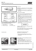
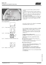
* Screw the Quicklinc fitting into the Zerk-Lock body and
tighten until parts will not tighten further (about 1-1/2
turns).
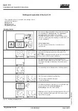
* If the lines are not primed, prime them before connecting
them to the Zerk-Locks.
* Connect feed lines (dia. 6x1.5 mm or 1/4) from the check
valves directly to existing grease fittings using the Zerk-
Lock
fittings included with the accessory kit.
Note: Push the end of the line firmly into the Quicklinc fitting
until it is fully seated in the body. The primed feed lines (dia.
6x1.5 mm) are marked with white lines (Fig.8, 9) as an
installation aid.
Fig. 7 - Screwing Quicklinc fitting into the Zerk-Lock body
Note: Quicklinc hex is 12 mm. Zerk-Lock body hex is 1/2
.
* Move the Zerk-Lock and tube fitting from side to side on
the grease fitting to insure the Zerk-Lock is firmly seated.
Fig. 9 - Feed line insert into the fitting up to the next white
mark
4157a98
Connection of Feed Lines
* Measure, cut and route the feedlines included in the kit.
Avoid sharp bends of the plastic tubing and the moving
parts of the machine that could damage the lubrication
lines. Minimum bending radius is 50 mm (2 in).
* Secure the lubrication lines to the machine using nylon
ties, clamps or straps provided in the accessory kit.
Fig. 8 Feed line installed in the Quicklinc fitting
* Cut the feed line off at one of the white lines before it is
mounted (see Fig. 9.).
* Then insert the feed line into the fitting up to the next
white mark.
This will ensure a correct installation of the feed line in
the tube fitting.
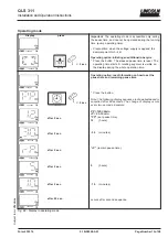
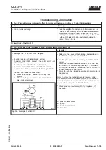
Filling of reservoir
* Fill the reservoir with a clean, suitable lubricant.
Fig. 10 - Vent hole on reservoir
Setting of lubrication cycle time interval
* Set the lubrication cycle time interval (see page 11 to 13).
4203a99
4202a99
4263a00