


Page Number 16 of 28
QLS 311
Subject
to
modifications
2.1B-38008-A01
Form 403074
Installation and Operation Instructions
Troubleshooting
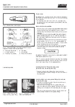
Pump of the QLS 311 system
Fault: pump motor doesnt run
Cause:
Power supply interrupted. Green decimal point On/h on
display is not lit.
* Check the voltage supply to the pump/
fuses. If necessary, eliminate the fault or
replace the fuses.
* Check the feed line from the fuses to the
plug of the pump and then to the printed
circuit board.
*
Initiate an additional lube cycle. Check
voltage supply from the printed circuit
board to the motor.
* Replace printed circuit board.
* Replace housing with key pad.
Remedy:
Power supply from printed circuit board to motor
interrupted.
Printed circuit board defective.
Key pad or button is defective.
EP
display at the key
pad flashes.
Fault: pump does not deliver lubricant
Cause:
Reservoir is almost empty.
LL
display at the key pad is
flashing.
Pump lost prime and
Er
display at the key pad is
flashing.
Air pockets in lubricant.
Improper lubricant has been used.
Suction hole of pump element clogged.
Pump piston is worn.
Check valve in pump element defective or clogged.
Remedy:
* Fill the reservoir with clean grease. Let the pump run
(initiate an additional lube cycle) until the lubricant
shows at all lube points.
Note: According to the ambient temperature and/or sort of
lubricant, the pump element needs no longer operation
time in order to reach the full pump capacity. Therefore, in-
iate several additional lube cycles.
*
Trigger an additional lubrication cycle. Lubricant must
dispense without air bubbles.
*
Change the lubricant.
*
Remove pump element. Check suction hole for foreign
particles. If there are any, remove them.
*
Replace pump element.
*
Replace pump element.
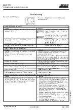
The green rotating display indicates that the pump
operates properly.
4209a99
Fault: Pump either does not switch off at all or only after the monitoring time of 15 min.
Cause:
Proximity switch is not dampened, i.e. the control pin
does not move within the switching range of the initiator,
or the distance between the control pin and the initiator
surface is more than 0.5 mm (0.02 in.).
Remedy:
* Initiate an additional lubrication. Check whether the
control pin moves centrically over the switching surface
of the initiator. In case the adjustments do not
correspond to the indications, the fixing position of the
metering device has to be corrected.
* Check the distance between the control pin and the
switching surface of the initiator (max. 0.5 mm; 0.02 in.).
In case the adjustments do not correspond to the
indications, the fixing position of the proximity switch
has to be corrected.
* Distances between the switching surface of the initiator
and the upper edge of the fixing nut:
* When the metering device is mounted at the back: 16
/
0,2 mm (0.62/-0.08 in.)
* When the metering device is mounted at the bottom:
12,7 +/0,1 mm (0.5 +/-0.004 in.).
* Tightening torque of the nut: 1,5 Nm (1.10 ft-lb).