Lincoln QLS 311 Installation And Operation Instructions Manual Download Page 4

Page Number 4 of 28

QLS  311

Subject 

to 

modifications

2.1B-38008-A01

Form 403074

Installation and Operation Instructions

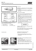
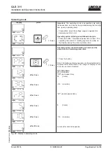
Installing Zerk-Locks onto grease fittings (for inch size

accessory kits only)

• The Zerk-Lock fitting consists of the Zerk-Lock body, an

insert and a Quicklinc fitting.

* Place the Zerk-Lock body over the grease fitting and

place the staking tool firmly against the Zerk-Lock insert.

(Staking tool is included in the accessory kits, see page

8).

* Strike the tool sharply with a hammer until the Zerk-Lock

insert partially crimps onto the grease fitting.

Fig. 5 - Place the Zerk-Lock

body over the grease fitting

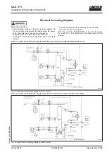
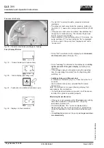
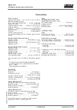
Fig. 4 - Internal feedback of supplied lubricant, only on

backside mounted SSV divider blocks

Check valves

Important:

  One  complete  check  valve  must  be  installed  in

each outlet port hole used, see Figs. 1 & 4 to avoid draining

the oil reservoir.

* For feedlines (dia. 6x1.5 mm, (1/4“) I.D., provided in the

accessory kits) use check valves with standard collar and

knurled  flange.

Fig. 3 -Check valve,  push-in type

4180a99

Fig.  6  -  Installation  of  Zerk-

Locks with staking tool

4201a99

4188b99

Lubrication points

4200a99

Installing Quicklinc fittings into lube points

(for metric size  accessory kits only)

* Remove hydraulic lube fittings from lube points and

install appropriate Quicklinc fittings into the bore holes of

the lube points.

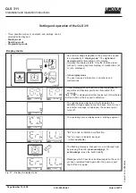
Return of lubricant quantities

• All QLS pumps with the 

back mounted SSV divider block

(vertical outlets) have the capability to return unused

lubricant from the distributor block directly to the reservoir

internally

.

• To achieve this automatically, 

outlet 2 has to be closed

with a closure plug (

see Fig. 4). Lubricant quantities of

pair and impair outlets are returnable via the connection

of outlets 1 and 2.

• For returning, always start with the oulets with the lowest

outlet numbers, i.e. 2, 4, 6... or 1, 3, 5... 

plus outlet 2

. As

shown in Fig. 4, the lubricant from outlets 1, 2 and 4 (3xR)

will be internally returned to the reservoir.

• The remaining outlets are to be used for the connection

to the lube point or to increase the lubricant quantity

(double or triple).

Important:

 If 

outlet 2

 is connected to a 

lube point

,

 outlet 1

must not be closed

, see Fig. 1.

Note:  To  return  unneeded  lubricant  quantities  from 

bottom

mounted divider blocks,

 connect unneeded outlet via feed-

line to return plug 5 (Fig. 15) for 

external

 return.

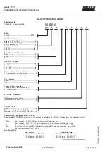
X - Outlet quantity (single...)

B - Oil supply

1...6  Outlet numbers

C - Oil included

A - Clamping ring (brass)

R - Return line borehole

Summary of Contents for QLS 311

Page 1: ...QLS 311 Lubrication System for Oil with integrated timer 2 1A 38008 A01 March 2001 Form 403074 Section Q3 Page 15A QLS 311 Installation and Operation Instructions 810 55241 1 4252a00...

Page 2: ...amage caused by poor or over lubrication Each outlet used must be equipped with an appropriate check valve see page 4 Fig 3 Don t paint pump Before painting machine or commerci al vehicle remove or co...

Page 3: ...lation Instructions Pump SSV Divider Block Crossporting of the SSV divider blocks Fig 1 Single double and triple lubricant output 4163a98 Fig 2 Closure plug provided in the accessory kits Install a cl...

Page 4: ...ing Quicklinc fittings into lube points for metric size accessory kits only Remove hydraulic lube fittings from lube points and install appropriate Quicklinc fittings into the bore holes of the lube p...

Page 5: ...e fitting from side to side on the grease fitting to insure the Zerk Lock is firmly seated Fig 9 Feed line insert into the fitting up to the next white mark 4157a98 Connection of Feed Lines Measure cu...

Page 6: ...cable 5 Control p c b None 0 Monitored 1 cycle SSV 12 SSV 18 Monitored 1 2 3 cycles SSV 6 SSV 8 1 Example of an explained model number Pump model P31131810111 oil pump SSV 6 block back mounted only 23...

Page 7: ...is undamaged and conforms to standards and the contacts are safe Connect the electric wires according to the following electrical connecting diagrams Note The protection IP6K9K NEMA 4 is guaranteed w...

Page 8: ...ternate current 120 230 VAC with integrated printed circuit board and attached SSV divider block 4254a00 Alternate current 120 230 VAC with integrated printed circuit board and external SSV divider bl...

Page 9: ...ng the lubricant to the SSV divider block When all lubrication points have received lubricant an internal proximity switch turns the motor off completing one lubrication cycle If pump does not complet...

Page 10: ...ing time Fig 20 If the voltage supply is interrupted during the operating time the operating time starts from the beginning after switching on Fig 20 Green display operating time Fig 19 Green decimal...

Page 11: ...d low level control In this case switch on the pump by pressing the button for additional lube cycle see Fig 21 Acknowledge the malfunction before doing so When a malfunction is present it can only be...

Page 12: ...key pad is defective The right hand decimal point On h indicates the available voltage supply during the pause time As soon as another message is displayed the decimal point turns off The operating ti...

Page 13: ...rotating segment is visible on the display during the whole operation time Operating option read information on how to set the pause time and remaining pause time Press the button Note The following d...

Page 14: ...he adjustment of the pause time in the operating mode again see page 12 Display press press Fig 29 Display in programming mode Programming options Pause time P1 0 99 hours P2 0 59 minutes Min pause ti...

Page 15: ...rts will void the pump warranty Turn off the voltage supply for pumps 120 VAC and 230 VAC before servicing the pump Important To clean the system use petroleum spirit or petroleum Do not use Tri Per o...

Page 16: ...he pump element needs no longer operation time in order to reach the full pump capacity Therefore in iate several additional lube cycles Trigger an additional lubrication cycle Lubricant must dispense...

Page 17: ...un refer to Initiating an additional lube cycle Disconnect all feed lines of the divider block one after the other If oil shows under pressure i e at outlet 3 Fig 32 the blockage is located in the lin...

Page 18: ...the divider block After removing the pistons mark them in order to reinstall them in the right direction and position They may not be interchanged Thoroughly clean the divider block body in a grease d...

Page 19: ...0 30 Operating current 2 0 A Operating voltage 24 V 20 30 Operating current 1 0 A Residual ripple in relation to the operating voltage 5 acc to DIN 41755 Note The pump motor is suitable for intermitte...

Page 20: ...S 311 Number of Outlets Dimensions A in mm in 8 75 2 95 12 105 4 13 18 150 5 90 Fig 33 Dimensions of QLS 311 2012b95 Number of Outlets Dimensions A in mm in 6 60 2 36 12 105 4 13 18 150 5 90 4233a99 F...

Page 21: ...ultural machines In such cases the check valves of the divider blocks must have a reinforced collar and a smooth flange Fig 37 Different types of check valves push in type Important Connect only high...

Page 22: ...1 Subject to modifications 2 1B 38008 A01 Form 403074 Installation and Operation Instructions Service Parts for the QLS 311 QLS 311 with back mounted SSV Divider Block 4250a00 Fig 40 QLS 311 with back...

Page 23: ...550 34004 1 4 Shaft x 1 550 36979 1 5 Intermediate plate x 1 450 24857 1 6 Eccentric gear x 1 550 36979 4 7 Housing x 1 550 34003 1 8 Floating switch x 1 450 24856 1 9 Pressure relief valve 80 bar x 1...

Page 24: ...of 28 QLS 311 Subject to modifications 2 1B 38008 A01 Form 403074 Installation and Operation Instructions QLS 311 with bottom mounted SSV Divider Block Fig 41 QLS 311 with bottom mounted SSV Divider...

Page 25: ...2A1 0 x 1 550 36984 2 Housing cover for low level control and VAC plug 1A1 0 x 1 550 36984 3 VAC plugs 1 2A1 0 x 1 550 36984 4 14 1 Appliance plug 1 with 10 m cable for power supply x 1 664 36078 7 1...

Page 26: ...ncoln Way St Louis MO 63120 1578 USA Phone 1 314 679 4200 Fax 1 800 424 5359 Europe Africa Heinrich Hertz Str 2 8 D 69183 Walldorf Germany Phone 49 6227 33 0 Fax 49 6227 33 259 Asia Pacific 25 Int l B...

Page 27: ...ica Lincoln GmbH Marketing Services Heinrich Hertz Strasse 2 8 Germany 49 6227 330 Fax 49 6227 33 259 Do you need a copy of this document in your language Simply find out the from below and fax it to...

Page 28: ...ica Lincoln GmbH Marketing Services Heinrich Hertz Strasse 2 8 Germany 49 6227 330 Fax 49 6227 33 259 Yes please send me the French version Name Company Address City State Postal Code Country Phone Se...

Reviews: