


Page Number 2 of 28
QLS 311
Subject
to
modifications
2.1B-38008-A01
Form 403074
Installation and Operation Instructions
Table of Contents
Safety Instructions ...................................................... 2
Installation Instructions ............................................... 3
Pump ............................................................................ 3
SSV Divider Block.......................................................... 3
Crossporting of the SSV Divider Block ......................... 3
Check valves ................................................................. 4
Feedback of supplied lubricant .................................... 4
Installing Zerk-Locks onto grease fittings ................... 4
Connecting Feed Lines ................................................ 5
Filling of reservoir .................................................... 5
Setting of lubrication cycle time intervall ................ 5
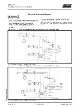
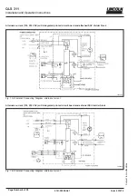
Electrical Connection Diagrams .................................. 6
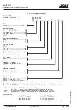
QLS 301Selection Guide .............................................. 7
Description of QLS 311 ................................................ 8
Operating of QLS 311 .................................................. 8
Pressure relief valve ..................................................... 9
Pump Display Window ................................................. 9
Monitoring time/malfunction ......................................... 9
Acknowledging the malfunction ............................ 10
Low-level control ................................................... 10
Acknowledging the low level indication ................ 10
Malfunction/low level indication ............................ 10
Monitoring relay ........................................................... 10
Metering of the lubricant ............................................. 10
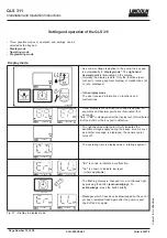
Setting and operation
of the QLS 311 ............................................................ 11
Display mode .............................................................. 11
Operating mode .......................................................... 12
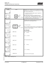
Programming mode ................................................... 13
Maintenance, Repair and Test .................................. 14
Maintenance ................................................................ 14
Refilling reservoir .................................................. 14
Repair .......................................................................... 14
Functional Test ............................................................ 14
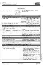
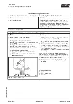
Troubleshooting ......................................................... 15
Technical Data ............................................................ 19
Dimensions ................................................................ 20
Service Parts of the QLS 311 .................................... 20
Manufacturers declaration ......................................... 24
Safety Instructions
Appropriate Use
Only use QLS 311 for the delivery of lubricants. The pump
is designed for intermittent operation. QLS 311 is desi-
gned for supplying lubricant to a
maximum of 18 lube
points per cycle
.
Do not use QLS 311 with SSV block in bottom mounting
position for mobile applications.
Dont install the pump in
areas exposed to shock.
General safety Instructions
Do not over pressurize reservoir when filling the pump.
Refill QLS 311 pump with clean lubricant.
Incorrect use may result in bearing damage caused by
poor or over lubrication.
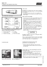
Each outlet used must be equipped with an appropriate
check valve (see page 4, Fig.3.).
Dont paint pump. Before painting machine or commerci-
al vehicle remove or completely cover the pump.
Unauthorized modifications or changes to an installed
system are not recommended and will void warranty. Any
modifications must be subject to prior consultation with
the manufacturer of the QLS 311.
Regulations for prevention of accidents
To prevent accidents, observe all city, state and federal
safety regulations of the country in which the product will
be used.
For pumps with 120 VAC and 230 VAC, switch off the
power supply before beginning maintenance or repair
work.
QLS 311 operates automatically. However, a regular
check (approximately every 2 weeks) should be made to
ensure that lubricant is being dispensed from all points.
Used or contaminated lubricants must be disposed of in
accordance with local environmental regulations, see
technical data sheets of lubricants.
The manufacturer will not accept any liability for:
- damage due to the use of greases which are not or are
only conditionally pumpable in centralized lubrication
systems.
- damage caused by insufficient lubricant and irregular
refilling of pump.
- damage caused by the use of contaminated lubricants.
- damage caused by inadequate disposal of used or
contaminated lubricants.
- damage caused by unauthorized modification of system
components.
- damage caused by the use of unapproved parts (voids
the pump warranty).
Operation, Repair and Maintenace
Repairs should only be performed by authorized
personnel who are familliar with the instructions.
Explanation of symbols:
= explanation
* = describes an action
- = listing within a section
QLS 311 must only operate with mounted or connected
SSV divider blocks.
Pump must be regularly refilled with clean lubricant.