


Subject
to
modifications
Page Number 3 of 28
2.1B-38008-A01
QLS 311
Form 403074
Installation and Operation Instructions
Installation
Do not remove, modify or alter any safety equipment
already installed on the machine.
QLS 311 pump must be kept away from heat sources
(see Operating Temperature Specification).
Follow installation instructions from the OEM regarding
minimum distances between the drilled holes and
welded procedures.
Use the following recommendations to select an
installation location:
- Keep the feed lines as short as possible.
- Provide access to fill, clean and visually monitor the
pump operation.
Installing QLS 311 pump with the reservoir upright is
perferred, but the pump may be installed with the reser-
voir in horizontal position without affecting its operation.
The QLS 311 may only be installed by qualified person-
nel. The connection (N/L/PE) of the supply voltage must
be made according to VDE 0100 and VDE 0160.
Install a protective and lock out device for isolating and
disconnecting the QLS 311. Before beginning the
installation, disconnect the electrical supply .
Failure to observe the safety instructions, i. e. touching
electrically charged parts when the system is opened, or
improper handling of the QLS 311 may
cause serious
injury or death
.
If the values specified in the Technical Data are excee-
ded, the device may overheat and damage the QLS 311
and thus impairing the electric system.
Installation Instructions
Pump
SSV Divider Block
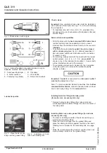
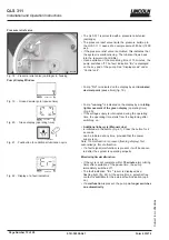
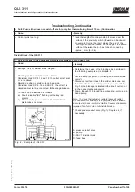
Crossporting of the SSV divider blocks
Fig.1 - Single double and triple lubricant output
4163a98
Fig. 2 - Closure plug, provided in the accessory kits
* Install a closure plug in each outlet port hole which is not
required, see Fig. 1 or 4.
1014b00
Use drilling template to mark and drill mounting holes of
the QLS 311. Drilling template and mounting bolts are
included in the package of the QLS 311.
Important:
In case of divider blocks mounted on the back,
remove the check valve installed on outlet 2 for the transport
of the QLS 311.
A simple output is the quantity of lubricant supplied by the
piston per stroke per outlet borehole to a lube point.
It
amounts to approx. 0.2 cm³.
The outlets of the SSV divider block can be combined to
increase the amount of lubricant for a particular outlet. To
do this, simply plug the unused outlets with the closure
plug (see Fig. 2), provided in the accessory kit.
Lubricant from a plugged outlet is redirected to the next
outlet on the same side of the SSV divider block in
descending numerical order (see Fig. 1).
For instance, plugging outlets 5 and 3 will triple the
amount of lubricant to outlet 1. The connecting channel to
outlet 2 is closed by means of the check valves clambing
ring (A).
Lubricant quantities not needed may be returned to the
reservoir (see Return to Reservoir).
Important: Do not plug outlet numbers 1 and 2
on SSV 8, 12
and 18 of pump models with SSV divider block installed on
the bottom (outlets in horizontal position).
x - Outlet quantity (single, double, etc.)
1....6 Outlet numbers
C - Oil included
A - Clamping ring (brass)
R - Return
B - Oil supply